Milnor 72044 WP2 Service Download Page 117

Ê

Replacing the Bearing Housing, Seal Sleeve, 

and Seals (Front or Rear)

1. With the seal sleeve removed, press all old seals out of the bearing housing. Remove the large o-ring from the

outside of the housing. Thoroughly clean the bearing housing and flush out all grease passages to make cer-
tain they are unblocked. Remove the o-rings from the inside of the seal sleeve and clean the seal sleeve.

2. While the bearing housing is dissassembled, charge all grease passages with grease. This will assure that there

are no blockages.

3. Replace the o-rings in the seal sleeve and the large o-ring on the outside of the bearing housing. Replace with

new o-rings if the old ones are worn.

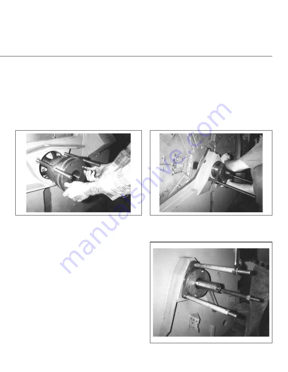
4. Press new seals into the bearing housing. You may gently work the seals in with a mallet and metal drift as

shown in FIGURE 5.  

Each seal must be of the proper material and face the proper direction. The type of material
and direction the seal faces may differ from one seal to another within the same bearing
housing and also from one type of machine to another. It is essential to consult the Main
Bearing Assembly drawing for your machine for the proper part number and direction to
face each seal.

5. Slip the seal sleeve into the bearing housing as shown in FIGURE 6 below right, using care not to damage or

fold under any of the seal lips. Be sure to insert the sleeve in the proper direction (see Bearing Assembly draw-
ing).

NOTE:  If both housings are being installed, install the rear housing first.

6. With two of the three temporary guide rods in position on the shell, place the bearing housing onto the guide

rods and install the seal sleeve setting fixture on to the bearing housing as shown in FIGURE 7.  The seal
sleeve setting fixture prevents the seal sleeve from being pushed out of the housing as the housing is in-
serted into the shell. Note that the seal sleeve setting fixture and the bearing setting fixture are very similar,
but the seal sleeve setting fixture has a longer hub. 

7. With a clean, lint free cloth, apply a coating of light machine oil to the outside of the housing, to assist in in-

stallation. Push the housing into the shell as shown in FIGURE 8. Once the housing is far enough into the
shell to support itself, place any shims back into position between the housing and the shell.  Remove, then
replace guide rods if required to place shims under bearing housing pads.

8. Install the third guide rod, spacers if required, and hex-

nuts, using these to seat the housing fully, as shown
in FIGURE 9. Remove the seal sleeve setting fix-
ture.  

9. Remove the guide rods and install the bearing housing

cap bolts. See “BOLT TORQUE REQUIRE-
MENTS” elsewhere, for proper torques.

10. With the grease gun, pump grease into the inner por-

tion of the bearing cavity, such that when the bear-
ing is installed, the space between the bearing and
the seals will be approximately 1/3 full of grease.

11 Proceed to “Measuring Unmounted Clearance . . .”

below, even if both the front and rear bearings are
being replaced. Once the rear bearing is installed,
the bearing housing replacement procedures may
then be repeated for the front (soil side) bearing hous-
ing.

Î

FIGURE 5 

(MSSM0303AE)

Î

Installing Seals in

Bearing Housing

Î

FIGURE 6 

(MSSM0303AE)

Î

Installing Seal Sleeve in 

Bearing Housing

Î

FIGURE 7 

(MSSM0303AE)

Î

Installing the Bearing Housing Setting

Fixture onto Housing (42" machine shown)

Î

FIGURE 8 

(MSSM0303AE)

Î

Pushing the Bearing Housing into the

Shell (60" Rapid-load machine shown)

Î

FIGURE 9 

(MSSM0303AE)

Î

Tightening the Bearing Housing

into the Shell (42" machine shown)

Summary of Contents for 72044 WP2

Page 1: ... ECN MPP72WE2AE 2001044N Publishing System TPAS Access date 01 24 2001 Document ECN s Latest Available Service 72044 WP2 WP3 Washer Extractors PELLERIN MILNOR CORPORATION POST OFFICE BOX 400 KENNER LOUISIANA 70063 0400 U S A ...

Page 2: ...ublishing system access date and whether the document ECN s are the latest available or exact References to Yellow Troubleshooting Pages This manual may contain references to yellow pages Although the pages containing troubleshooting procedures are no longer printed on yellow paper troubleshooting instructions if any will be contained in the easily located Troubleshooting chapter or section See th...

Page 3: ...74113A 38 Location Lube Points WED BMP701313 71143A 39 Fastener Torque Requirements MSSM0101CE 9906AV 59 Section 2 Shell and Door Assemblies 60 Door Seal Replacement on Rapid Load Models MSSMA413AE 8530BV 64 7244 WE3 Staph Guard Door Assembly BMP790020 79492A 65 Parts List Door Assembly 7244WE3 SG BMP790020R 98301V 66 60 72 WEH Shell Door Assembly BMP780109 81433B 67 Parts List Shell Door Assembly...

Page 4: ... Guard BMP701672R 71051 122 Suspension Adjustments for Divided Cylinder Machines MSSM0302AE 8414BV 128 Hydro Cushion Suspension Cylinder 7244 Rapid Load Staph Guard BMP701629 71047 129 Parts List Suspension Cylinder Assembly BMP701629R 73261A 131 Suspension Cylinder Locations BMP701235 2000133V 132 Push Down Assembly BMP701671 70526 133 Parts List Push Down Assembly BMP701671R 70526 134 7244WE3 Cy...

Page 5: ... 72431A 169 Burket Steam Valve BMP800020 96066V 170 Steam Sparger Assemblies BMP900001 96132V 173 Section 9 Pneumatic Piping and Assemblies 174 3 Way Pilot Valves BMP900032 91182V 175 Asco 3 way Solenoid Valves BMP701359 97086V 177 ASCO N C Valve Assembly BMP701394 71463A 178 Parts List ASCO N C Valve BMP701394R 81377A 179 Universal Airvalve Box Assembly BMP780088 83457C 180 Parts List Universal A...

Page 6: ......

Page 7: ...before the changes the new manual covers only new machines Example Discard MAT MODELAE 8739CV when MATMODELAE 8739DV is received minor improvements Also discard MAT MODELAE 8739DV when MATMODELAE 8746AV is received major improvements But keep MATMODELAE 8746FV when MATMODELBE 8815AV is received since the new manual no longer applies to machines originally shipped with the old manual Ë Documents an...

Page 8: ......

Page 9: ...points brake and clutch linings and similar parts are not covered by this warranty nor are parts damaged by exposure to weather or to chemicals We reserve the right to make changes in the design and or construction of our equipment including purchased components without obligation to change any equipment previously supplied ANY SALE OR FURNISHING OF ANY EQUIPMENT BY MILNOR IS MADE ONLY UPON THE EX...

Page 10: ...6 In correspondence regarding motors or electrical controls please include all nameplate data including wiring diagram number and the make or manufacturer of the motor or controls All parts will be shipped C O D transportation charges collect only Please read this manual It is strongly recommended that you read the installation and operating manual before attempting to install or operate your mach...

Page 11: ...sufficient clearance for machine movement Provide any safety guards fences restraints devices and verbal and or posted restrictions necessary to prevent personnel machines or other moving machinery from accessing the machine or its path Provide adequate ventilation to carry away heat and vapors Ensure service connections to installed machines meet local and national safety standards especially reg...

Page 12: ...ing machine Ê Hazards During Service and Maintenance ELECTROCUTION HAZARD High voltage is present inside electric boxes mo tors and many other components Power switches on machine control panels disable only control circuit power in certain boxes You can be killed or seri ously injured on contact with high voltage Lock OFF and tag out power at the wall disconnect before servicing except where spe ...

Page 13: ...ts including but not limited to safety limit switches electrical interlocks and operator controls If any of these conditions occur The machine makes a sound like skidding automobile tires as it comes out of extract The wash or drain clutch does not disengage or it reengages during extract V belts jump off at the start of during or at the end of extract A strange whining sound occurs at any time du...

Page 14: ...ven fall over if the tilt wheels at the non tilted end are raised out of their cradles killing injuring personnel and or damaging property NEVER manually tilt lift both ends of the machine at the same time One end must always be seated in its cradle ALWAYS visually inspect the tilt wheels to be sure they are all fully seated in their cra dles before each manual tilt up Hydraulic valve manual opera...

Page 15: ...and used to support the machine during servicing Read all safety instructions before performing maintenance Tall safety stands Tall safety stands Short safety stands 48032 48036 52038 and 72044 dual pivot tilting washer extractor models All except J2N models 64040 64042 64046 72046 72058 and 72075 single pivot tilting washer extractor models J2N models Centrifugal extractor models Short safety sta...

Page 16: ...trong and rigid enough and has not subsided to leave the floor slab suspended without support on grade installations can often be made directly to an existing floor slab if it has enough strength and rigidity to safely withstand our published forces without transmitting undue vibration If the subsoil has subsided or if the floor slab itself has insufficient strength and rigidity a deeper foundatio...

Page 17: ...ating speeds of the machine s compared to the natural frequencies of the floor and or any other supporting structure s A qualified soil and or structural engineer must be engaged for this purpose Figure 1 How Rotating Forces Act on the Foundation Typical Machine Legend A Direction of force B Load C Rotation Frequency RPM 60 Figure 1 above is intended to depict both on grade and above grade install...

Page 18: ...ete instructions before continuing Do not jack the machine here Do not lift the machine here Use three point or four point lifting as determined by the lifting eyes furnished Rig the load using lifting cables of sufficient size and length to ensure cables are not over stressed Do not lift the machine from one corner or one side edge ...

Page 19: ...s or brackets also painted red may be provided with this machine Do not discard safety stands or brackets Do not step or stand on this machine part Maintain a 25 mm 1 minimum clearance between float clips Set low level so that the bottom of the float is always at least 25mm 1 above the bottom of the float tube This motor or pump should rotate in the direction of the arrow This is the hot water inl...

Page 20: ...t with this tag is installed on the machine Do not remove this component from the machine Install the appropriate part here before operating the machine Do not strap or chain over box 7 _ccQbi _V DQW 9 ecdbQdY_ c Cec U TUT GQcXUb 5hdbQSd_bc ...

Page 21: ... During drain and extract the cylinder must rotate clockwise when viewed from here Do not strike shell front of washer extractors during fork lifting Striking shell front will cause door to leak Brake assembly under machine is fragile Forklift blades should only be placed under main structural beams C9E ED715 1F ...

Page 22: ...bearing air pad gauge at 10 psi 70 kg cm2 64 and 72 ExN and JxN models only Set disc brake air gauge at 10 psi 70 kg cm2 64 and 72 ExN and JxN models only 7 _ccQbi _V DQW 9 ecdbQdY_ c Cec U TUT GQcXUb 5hdbQSd_bc ...

Page 23: ...Section 1 Service and Maintenance ...

Page 24: ...ANGLE AND CRUSH HAZARD Belts and pulleys can entangle and crush body parts Lock OFF and tag out power at the wall disconnect before servicing except where specifically instructed otherwise in this section Insure belt and pulley guards are in place during service procedures Permit only qualified maintenance personnel to perform these procedures CRUSH SEVER HAZARD Tilting mechanism can crush or seve...

Page 25: ...maging as under lubrica tion Where quantities are stated in strokes one stroke of the grease gun is assumed to provide 0624 fluid ounces 1 77 grams by volume of grease Therefore one fluid ounce 28 3 grams of grease would be pro vided by 16 strokes of the grease gun Determine the flow rate of your grease gun by pumping one ounce into a calibrated container If fewer than 16 strokes are required all ...

Page 26: ...er v belts and tighten if necessary NOTE 3 All v belts are not alike Super or High Capacity v belts frequently have considerably higher capacities than Standard belts Sometimes one brand of v belt is more suitable than another brand of v belt although both v belts are interchangeable It is always best to purchase replacement belts from the original manufacturer of the equipment Purchasing exact re...

Page 27: ...xcess grease to escape thus avoiding over heating This escaping lubricant need not be replaced Every time these bearings are lubricated the surplus grease will come out of the spring loaded relief fittings after a few hours running time NOTE 6 Bearings can run hot enough to make it extremely uncomfortable for a person to hold his hand on the bearing housing for more than a few seconds This is norm...

Page 28: ...ne stroke at one location 48 Open pocket main bearings and seals FIGURE 11 NOTES 4 5 and 6 Front and rear bearing grease fitting 0 31 ounces 8 85 grams five strokes at two locations Seal grease fitting See Semi Annual Maintenance Items in this section 52 and 72 Open pocket main bearings and seals FIGURE 11 NOTES 4 5 and 6 Front bearing grease fitting 1 87 ounces 53 1 grams thirty strokes at one lo...

Page 29: ...Divided Cylinder and Staph Guard only Î F IGURE 16 MSSM0201CE Î 4 2 Staph Guard ldler Shaft Grease Fitting Î F IGURE 17 MSSM0201CE Î 6 0 and 72 Staph Guard Idler Shaft and Disc Brake Grease Fittings 60 shown Î F IGURE 18 MSSM0201CE Î T ypical Jackshaft Grease Fittings 52 machine shown LUBRICATION AND PREVENTIVE MAINTENANCE FOR HYDRO CUSHION MACHINES MSSM0201CE 9840AV 6 of 11 ...

Page 30: ...ions Disc brake 60 and 72 Staph Guard only Grease fittings FIGURE 17 0 12 ounces 3 54 grams two strokes at one location Jackshaft if equipped Grease fittings FIGURE 18 NOTES 5 and 6 0 12 ounces 3 54 grams two strokes at two locations Water pressure regulator if equipped Gauge FIGURE 19 28 psi 0 14 kg cm 2 Foundation Anchor bolts and grout Check condition Tilt wheels 42 48 and 72 Tilt Models Grease...

Page 31: ...Î F IGURE 23 MSSM0201CE Î B rake Shoes all machines Î F IGURE 24 MSSM0201CE Î D isk Brake Staph Guard only Î F IGURE 25 MSSM0201CE Î H ydraulic Tilt Pressure Gauge On rear of 42 48 and 72 tilt models Î F IGURE 26 MSSM0201CE Î D oor Seal Pressure Regulator LUBRICATION AND PREVENTIVE MAINTENANCE FOR HYDRO CUSHION MACHINES MSSM0201CE 9840AV 8 of 11 ...

Page 32: ...59 Bar Door seal pressure regulator FIGURE 26 Check settings with machine in bare manual and clockwise wash rotation See instructions for operating individual outputs in the reference manual 42 and 48 Open pocket 48 50 PSI 3 37 3 51Kg cm 2 60 and 72 Rapid load 25 28 PSI 1 76 1 97 Kg cm 2 60 and 72 Staph Guard 18 20 PSI 1 27 1 41 Kg cm 2 Gear reducer Air vent FIGURE 27 Check vent for air leaks Air ...

Page 33: ...SI 21 0 35 Kg cm 2 Tilt position pressure regulator and gauge Check pressure in a wash step 30 PSI 2 11Kg cm 2 Hydraulic system tilting machines only NOTE 9 Oil filter Change filter Push down control valves 72 Rapid load and Staph Guard FIGURE 31 and NOTE 11 Observe operation and adjust if required Recirculation 48 dye models only FIGURE 32 Replace hose Î F IGURE 30 MSSM0201CE Î P ush Back and For...

Page 34: ...n a heavy soil environment NOTE 10 52 and 72 machine are not equipped with a tilt pressure regulator or gauge NOTE 11 Adjust push down control valves so that machine moves down evenly and all push down sockets meet simultaneously If the back of the machine comes down first close the valve slowly If the front comes down first open the valve Î F IGURE 33 MSSM0201CE Î T ypical Gear Reducer Fill and D...

Page 35: ...ushions Motors Commutator cam Balancing mechanism Disc brake if so equipped Hydraulic tilt mechanism Door latches Other grease points Open Pocket Machines 30015 20 22 C S and M 30 3022F8J 220 220 36021Q4x 36026Q4x 36021BWP Wells 1540 36021Q6x 36026Q6x 42024Q4x 42026Q6x EPLF 2 220 EPLF 2 36030Fxx 1030 DOT 3 42032Fxx 42026QHP 48032BHP BTL BTN 48036QHP QTL QTN 220 220 1030 Door EPLF 2 52038WP1 WTL WT...

Page 36: ... cWT fP SXbR TRc QTU aT bTaeXRX V a X PRR aSP RT fXcW UPRc ah bTaeXRT _a RTSdaTb 41 75B 5 dQ W U Q T 3becX 8QjQbT 2 cPRc fXcW eX V R _ T cb a P h Xb PcTS Qh VdPaSb R eTab P S _P T b RP T cP V T P S RadbW h da X Qb CWTbT R _ T cb eT Pdc PcXRP h 3 c bTaeXRT PRWX T d Tbb dP XUXTS P S PdcW aXiTS RZ 55 P S cPV dc _ fTa Pc cWT fP SXbR TRc QTU aT bTaeXRX V a X PRR aSP RT fXcW UPRc ah bTaeXRT _a RTSdaTb 3...

Page 37: ... conditions Multiply 5 service condition multiplier value by 9500 hours recommended lubrication interval 4750 hours calculated lubrication interval Table 4 shows that the amount of grease to be added is 0 32 ounces 9 1 grams Table 1 Determining the Service Condition Severity of Service Maximum Ambient Temperature Atmospheric Contamination Type of Bearing Standard 104o F 40o C Clean little corrosio...

Page 38: ...ings must be lubricated more frequently Divide the listed lubrication interval by two Table 4 Lubrication Amounts per Frame NEMA IEC Frame Size Bearing Description These are the Large bearings Shaft End in each frame size Note 4 Largest bearing in size category OD D mm Width B mm Grease gun strokes Note 5 Volume of grease to be added ounces grams Up to 215 132 6307 80 21 2 5 0 16 4 7 254 to 286 16...

Page 39: ...n 16 strokes are required the number of strokes should be increased Before starting lubrication make sure your grease gun is working and that you get a full charge of grease with every stroke Do not over lubricate motors Over lubrication of a motor can seriously damage it by forcing grease into motor windings Over lubrication of the extract motor can force grease into the centrifugal switch causin...

Page 40: ......

Page 41: ...w 3 8 16 X 1 1 4 15K100 15K100 15K100 5 Water Level Clamp Ring 2 19128 2 19128 3 6075 6 Airmount Firestone 3582 01 7264 60B100 60B100 7 Lower Belt Guard W O AUTOSPOT 2 19111 2 19111 3 6095 Lower Guard W AUTOSPOT 2 175043 2 175043 3 6095 8 Upper Belt Guard W O AUTOSPOT 2 19110 2 19110 3 6099 Upper Belt Guard W AUTOSPOT 2 185045 2 175045 3 6099 9 Excursion Switch 9R008 9R008 9R008 10 Marker Water Le...

Page 42: ......

Page 43: ......

Page 44: ......

Page 45: ... data Actual allowable torques are application dependent and can vary for many reasons joint types gaskets etc Use these values as a guide 5 Although FIGURE 1 depicts hex head bolts the table applies to all head types Ê Fasteners and Threadlocker Ë How Fasteners Loosen Standard threaded fasteners are manufactured with a clearance fit for easy assem bly With the fastener at the proper torque 85 of ...

Page 46: ...rimer N Allow to dry 3 Insert bolt into through hole assembly 4 Apply several drops of threadlocker onto bolt engage ment area 5 Assemble and tighten nut to correct torque for the threadlocker Ë Blind Holes See FIGURE 4 1 Clean all threads bolt and nut with cleaning solvent 2 Spray all threads with Loctite Primer N Allow to dry 3 Squirt several drops down female threads into bottom of hole 4 Apply...

Page 47: ...octite 277 Bare 1 4 20 SAE Grade 1 ASTM A307 2 5 3 39 3 0 4 06 3 3 4 47 3 6 4 88 4 6 6 23 4 3 5 83 3 3 4 47 SAE Grade 2 4 1 5 56 4 9 6 64 5 5 7 45 6 0 8 13 7 7 10 44 7 1 9 63 5 5 7 46 SAE Grade 4 4 8 6 50 5 8 7 86 6 4 8 67 7 0 9 49 9 0 12 20 8 3 11 25 6 4 8 67 SAE Grade 5 ASTM A449 6 3 8 54 7 6 10 3 8 4 11 38 9 3 12 60 11 8 15 99 11 0 14 91 8 4 11 39 SAE Grade 7 7 9 10 7 9 4 12 7 10 5 14 23 11 5 1...

Page 48: ...3 99 13 6 18 44 ASTM A354 Grade BC Ï All values in foot pounds and Newton meters Nominal bolt size Grade Designation and Standard Zinc or Cadmium Plated If instructions call for Loctite 222 or262 Loctite 242 Loctite 271 Loctite 272 Loctite 277 Bare 5 16 18 SAE Grade 1 ASTM A307 5 1 6 91 6 2 8 40 6 8 9 22 7 5 10 17 9 6 13 02 8 9 12 07 6 8 9 22 SAE Grade 2 8 5 11 52 10 2 13 83 11 3 15 32 12 5 16 95 ...

Page 49: ... 27 1 36 74 ASTM A354 Grade BC Ï All values in foot pounds and Newton meters Nominal bolt size Grade Designation and Standard Zinc or Cadmium Plated If instructions call for Loctite 222 or 262 Loctite 242 Loctite 271 Loctite 272 Loctite 277 Bare 3 8 16 SAE Grade 1 ASTM A307 9 0 12 20 10 8 14 64 12 0 16 27 13 1 17 76 16 7 22 64 15 5 21 01 12 0 16 27 SAE Grade 2 14 9 20 20 17 9 24 27 19 9 26 98 21 9...

Page 50: ... 41 64 0 86 77 49 2 66 70 ASTM A354 Grade BC Ï All values in foot pounds and Newton meters Nominal bolt size Grade Designation and Standard Zinc or Cadmium Plated If instructions call for Loctite 222 or 262 Loctite 242 Loctite 271 Loctite 272 Loctite 277 Bare 7 16 14 SAE Grade 1 ASTM A307 14 0 18 98 17 0 23 04 19 14 25 95 21 0 28 47 27 0 36 60 25 0 33 89 19 0 25 76 SAE Grade 2 24 0 32 54 28 8 39 0...

Page 51: ... 35 ASTM A354 Grade BC Ï All values in foot pounds and Newton meters Nominal bolt size Grade Designation and Standard Zinc or Cadmium Plated If instructions call for Loctite 222 or262 Loctite 242 Loctite 271 Loctite 272 Loctite 277 Bare 1 2 13 SAE Grade 1 ASTM A307 22 0 29 83 26 0 35 25 29 38 39 83 32 0 43 39 41 0 55 59 38 0 51 52 29 0 39 32 SAE Grade 2 36 6 49 62 43 9 59 52 48 8 66 16 53 6 72 67 ...

Page 52: ...51 120 0 162 70 ASTM A354 Grade BC Ï All values in foot pounds and Newton meters Nominal bolt size Grade Designation and Standard Zinc or Cadmium Plated If instructions call for Loctite 222 or 262 Loctite 242 Loctite 271 Loctite 272 Loctite 277 Bare 9 16 12 SAE Grade 1 ASTM A307 32 0 43 39 38 0 51 52 42 19 57 20 46 0 62 37 59 0 80 00 55 0 74 57 42 56 94 SAE Grade 2 52 7 71 45 63 3 85 82 70 3 95 31...

Page 53: ...1 6 232 66 ASTM A354 Grade BC Ï All values in foot pounds and Newton meters Nominal bolt size Grade Designation and Standard Zinc or Cadmium Plated If instructions call for Loctite 222 or 262 Loctite 242 Loctite 271 Loctite 272 Loctite 277 Bare 5 8 11 SAE Grade 1 ASTM A307 44 59 66 52 70 50 58 2 78 90 64 86 77 81 109 82 76 103 04 58 78 64 SAE Grade 2 72 7 98 57 87 2 118 23 96 9 131 38 106 6 144 53...

Page 54: ... 8 422 74 239 8 325 13 ASTM A354 Grade BC Ï All values in foot pounds and Newton meters Nominal bolt size Grade Designation and Standard Zinc or Cadmium Plated If instructions call for Loctite 222 or 262 Loctite 242 Loctite 271 Loctite 272 Loctite 277 Bare 3 4 10 SAE Grade 1 ASTM A307 77 104 40 93 126 09 103 1 139 78 113 153 20 144 195 24 134 181 68 103 139 65 SAE Grade 2 129 4 175 44 155 3 210 55...

Page 55: ...569 44 ASTM A354 Grade BC Ï All values in foot pounds and Newton meters Nominal bolt size Grade Designation and Standard Zinc or Cadmium Plated If instructions call for Loctite 222 or 262 Loctite 242 Loctite 271 Loctite 272 Loctite 277 Bare 7 8 9 SAE Grade 1 ASTM A307 124 7 169 07 149 6 202 83 166 3 225 47 182 9 247 98 232 8 315 63 216 1 293 0 166 3 225 47 SAE Grade 2 124 7 169 07 149 6 202 83 166...

Page 56: ...4 668 3 906 09 ASTM A354 Grade BC Ï All values in foot pounds and Newton meters Nominal bolt size Grade Designation and Standard Zinc or Cadmium Plated If instructions call for Loctite 222 or 262 Loctite 242 Loctite 271 Loctite 272 Loctite 277 Bare 1 8 SAE Grade 1 ASTM A307 187 5 254 22 225 0 305 06 250 0 338 95 275 0 372 85 350 0 474 54 325 0 440 64 250 0 338 95 SAE Grade 2 187 5 254 22 225 0 305...

Page 57: ... 1483 49 1393 0 1888 66 1293 5 1753 73 995 0 1349 04 ASTM A354 Grade BC Ï All values in foot pounds and Newton meters Nominal bolt size Grade Designation and Standard Zinc or Cadmium Plated If instructions call for Loctite 222 or 262 Loctite 242 Loctite 271 Loctite 272 Loctite 277 Bare 1 14 SAE Grade 1 ASTM A307 210 0 284 72 252 0 341 66 280 0 379 63 308 0 417 60 392 0 531 48 364 0 493 52 280 0 37...

Page 58: ...88 1 1746 43 ASTM A354 Grade BC 844 8 1145 40 1013 8 1374 53 1126 4 1527 20 1239 0 1679 86 1577 0 2138 13 1464 3 1985 33 1126 4 1527 20 Ï All values in foot pounds and Newton meters Nominal bolt size Grade Designation and Standard Zinc or Cadmium Plated If instructions call for Loctite 222 or 262 Loctite 242 Loctite 271 Loctite 272 Loctite 277 Bare 1 1 8 12 SAE Grade 1 ASTM A307 297 4 403 22 356 9...

Page 59: ...STM A354 Grade BC 1192 4 1616 68 1430 9 1940 04 1589 8 2155 48 1748 8 2371 05 2225 8 3017 78 2066 8 2802 20 1589 8 2155 48 Ï All values in foot pounds and Newton meters Nominal bolt size Grade Designation and Standard Zinc or Cadmium Plated If instructions call for Loctite 222 or 262 Loctite 242 Loctite 271 Loctite 272 Loctite 277 Bare 1 1 4 12 SAE Grade 1 ASTM A307 414 8 562 40 497 8 674 93 553 1...

Page 60: ... 2 3229 83 ASTM A354 Grade BC 1563 6 2119 96 1876 4 2544 06 2084 8 2826 61 2293 3 3109 30 2918 8 3957 37 2710 3 3674 68 2084 8 2826 61 Ï All values in foot pounds and Newton meters Nominal bolt size Grade Designation and Standard Zinc or Cadmium Plated If instructions call for Loctite 222 or 262 Loctite 242 Loctite 271 Loctite 272 Loctite 277 Bare 1 3 8 12 SAE Grade 1 ASTM A307 559 5 758 58 671 3 ...

Page 61: ...ASTM A354 Grade BC 2074 9 2813 20 2489 9 3375 85 2766 6 3751 01 3043 2 4126 03 3873 2 5251 36 3596 5 4876 20 2766 6 3751 01 Ï All values in foot pounds and Newton meters Nominal bolt size Grade Designation and Standard Zinc or Cadmium Plated If instructions call for Loctite 222 or 262 Loctite 242 Loctite 271 Loctite 272 Loctite 277 Bare 1 1 2 12 SAE Grade 1 ASTM A307 734 1 995 30 880 9 1194 34 978...

Page 62: ...24 21 6 29 28 22 6 30 64 17 7 24 00 13 1 17 76 7 16 14 31 3 42 44 32 8 44 47 26 4 35 80 19 0 25 76 7 16 20 33 3 45 15 34 8 47 18 27 3 37 00 20 2 27 38 1 2 13 43 1 58 43 45 2 61 28 35 2 47 72 26 1 35 38 1 2 20 45 1 61 14 47 1 63 86 36 9 50 00 27 3 37 00 9 16 12 56 8 77 00 59 4 80 53 46 5 63 04 34 4 46 64 9 16 18 62 7 85 00 65 6 88 94 51 3 69 55 38 0 51 52 5 8 11 92 5 125 41 96 7 131 10 75 6 102 50 ...

Page 63: ...06 20 234 6 318 07 183 8 249 20 1 14 259 2 351 43 270 8 367 16 212 1 287 57 166 3 225 47 1 1 8 7 413 0 559 95 432 0 585 71 337 0 456 91 265 0 359 29 1 1 8 12 390 0 528 77 408 0 553 17 318 0 431 15 251 0 340 31 1 1 4 7 523 0 709 09 546 0 740 28 428 0 580 30 336 0 455 55 1 1 4 12 480 0 650 80 504 0 683 33 394 0 534 19 308 0 417 60 1 1 2 6 888 0 1203 97 930 0 1260 91 727 0 985 68 570 0 772 82 1 1 2 1...

Page 64: ......

Page 65: ...Section 2 Shell and Door Assemblies ...

Page 66: ... and aligned into the door cavity close both doors and inflate Check to see that seals contact each other along the seam between the doors and that the seal contacts the shell front all around To check this attempt to slide a piece of paper between these surfaces 6 If the seal does not contact the shell at locations A or D see FIGURE 1 open the doors and stretch the seal toward these points 7 If s...

Page 67: ... can be moved in any direction for centering by loosening the 1 2 hex cap nuts which hold the door assembly to the hinge cross brace as shown below Location A Seals must contact each other and shell front Location C Seals must not drag against shell when door opens Location D Seal must contact shell front Location B Seals must contact each other and shell front Î FIGURE 1 MSSMA413AE Î Door Seal Ch...

Page 68: ...nto striker plates bolted to the shell front If the hole in these striker plates becomes worn the shell doors will be allowed to move while the machine is in operation It will look as though the doors are breathing This will cause rapid wear and premature seal failure Striker plate components are shown below Double Thickness Abnormal Inflated Condition Normal Inflated Bent Retaining Channel Î FIGU...

Page 69: ...e blowouts and too low air pressure will cause not enough contact between seal and shell front thus movement and rapid wear Kit K28 0011 which contains a fixed at 25 to 28 PSI regulator plus a pressure gauge is available from the Milnor factory If yours is inoperative it should be replaced Ë Check Door Bumper Be sure large rubber bumper part number 60C075 on right hand door is in place and not wor...

Page 70: ......

Page 71: ...0 OD all 18 60E004TE 04Z 1 4 OD X 170 ID NYL TUBING all 19 60E005 TUBING 5 16 OD POLY FLOW 55P FOOT all 20 51V010 TEE PIPE 1 8 BRASS FORGING TYPE all 21 53A047H MALCON 5 16X1 8POLY PH 68P 5 2 all 22 12P016 01Z CABLE CLMP BLACK UL APPROVED A 23 W3 06126 93072D SHELLDOOR 72SG2 3 SOILSIDE SOIL DOOR B 23 W3 06127 93072 SHELLDOOR 72SG2 3 CLEANSID CLEAN DOOR all 24 02 18181 78333A FITTING BRASS FOR INNE...

Page 72: ......

Page 73: ...95 HXCPSCR 3 8 16UNC2AX1 GR5 ZINC CAD all 8 03 06068 70358C PLATE DOOR OPENING 1 72WED USED ON SA 36 010 all 8 02 18961 91071C PLATE DOOR OPENING 60WED USED ON SA 28 122 all 9 02 175134 71143A PATCH SHELL DOOR GASKET all 10 02 175131 82231B PLATE LATCH MOUNT RT 60 72WE all 11 15K039 HXCAPSCR 1 4 20UNC2AX3 4 GR5 ZNC CD all 12 15U180 LOCKWASHER MEDIUM 1 4 ZINCPL all 13 15U185 FLATWASHER USS STD 1 4 ...

Page 74: ... 36 15N117 RDMACSCR 10 24UNC2X3 8SS18 8 all 37 24G018N ROLLED WASHER 194 ID NYLTITE 10W all 38 15G121 HXCAPNUT 10 24UNC2 3266BR NKLPLTG2 all 39 15P010 12Z PHILPAN TRDCUTSCRTYP10 24X1 2SS all 40 AAM36001R 82246J PIPING SEAL LATCH RITE 72WED all 41 53A031B BODY MAL90ELL1 4X1 8COMPPH 269C 42B all 42 60E004TE 04Z 1 4 OD X 170 ID NYLON TUBING all 43 53A039B BODY BRMAL90 5 16X1 8COMP B69A 5A all 44 53A0...

Page 75: ...uit prevents the doors from being opened for 7 1 2 seconds This allows the seals time to deflate before the doors are open The air operated vacuum pump is mounted on the side of the main valve set The two valves the relay and the time delay for the vacuum pump is shown on the wiring diagram that was shipped with the machine The two valves that operate the vacuum pump are labeled deflator enable an...

Page 76: ......

Page 77: ...ration Parts List Door Interlock WED Door Interlock WED BMP701654R 70481 Sheet 1 of 1 ASSEMBLIES 1 15K038 Cap Screw Hex Head 1 4 20 X 3 4 2 15U180 Lockwasher 1 4 3 15U185 Flatwasher 1 4 4 15K031 Cap Screw Hex Head 1 4 20 X 1 2 5 9R012 Micro Switch BZE RN125 6 2 18952 Striker Switch Bracket Left 7 2 18979 Striker Switch Bracket Right 8 2 18953 Striker Plate Left 9 2 18978 Striker Plate Right 10 2 1...

Page 78: ...ts list to the illustration Parts List Door Latch Assembly BMP701316 98183V Sheet 1 of 1 ASSEMBLIES A SA 10 020 90516B DOORLATCH ASSY SMALL COMPONENTS all 1A 02 10188 CYLINDER DOORLATCH all 1B 02 10188L 97087 CYL DR LATCH W TAP LEFT SIDE all 2 02 10222 82391B SPRING DOOR LATCH BALCOM all 3 02 10221 RETAINER DOORLATCH SPRING all 4 Y2 10314 70256B PLUNGER DOOR INTERLOCK all 5 60C112 ORING 5 8 ID 3 3...

Page 79: ...Section 3 Drive Assemblies ...

Page 80: ...h while the drain motor and the extract motors merely coast As soon as the drain valve opens the wash motor is shut off and coasts with the extract motors while the drain motor drives the cylinder through the reducer and clutch During extraction both the wash and drain motors are shut off the clutch disengages and the extract motor drives the cylinder through the jackshaft pulley and main V belt d...

Page 81: ...detrimental to the motor If voltage fluc tuations are not detected yet the symptom persists then the motor will probably soon fail A slow running motor may indicate a bad rotor whereas a loud or unusual noise likely indicates worn bearings If possible make immediate repairs to avert complete failure If this is not possible make sure replacement parts will be on hand when needed Note however that i...

Page 82: ...tified below Ë To Remove a Pulley 1 See FIGURE 2 2 Remove the belts Release belt tension by adjusting the position of the component to which the pulley is attached with the jack screws until the belts easily slip off of the sheave Do not force belts off by using a pry bar or roll ing the sheave 3 Loosen all three bushing cap screws 4 Put two cap screws into the push off holes in the bushing flange...

Page 83: ...shown in FIGURE 3 were supplied 4 Carefully tighten the cap screws alternately and progressively until the taper is seated approximately the In itial Torque as shown in the Taperlock Bushing Bolt Torque Specs elsewhere herein Rotate the sheave to detect any wobble or runout see FIGURE 2 next page 5 Install the belts onto the sheaves driving and driven and with the slack of each belt on the same si...

Page 84: ... final torque check When properly mounted the gap between the bushing flange should not be less than 078 nor more than 130 8 Check for proper belt tension and adjust if required See V BELT TENSION ADJUSTMENTS see Table of Contents Ï Taperlock Bushing Bolt Torque Specifications Size Code Stamped on bushing Bolt Size All National Coarse Thread Initial torque in lb Final torque in lb G 1 4 x 5 8 48 1...

Page 85: ...onnection near the clutch The quick release valve is necessary for the clutch used on Milnor washer extractors and is furnished as original equipment The air supplied to the clutch must be free of oil and moisture If the machine makes a loud screeching sound like skidding automobile tires during decel eration from extract speed to wash speed turn the Master switch to off immediately and refer to t...

Page 86: ... components should be replaced at this time if they show appreciable wear It is highly recommended to replace the belts that drive the clutch drum pulley unless these are brand new Ë To Replace the Gear Reducer and Clutch Reassemble all components in reverse order of their re moval Remember that all components such as motors brake etc must be properly adjusted using the align ment procedures descr...

Page 87: ... i e an extended squealing sound 9 If any of the above symptoms are observed repeat the alignment procedures Ê Jackshaft Replacement 52 60 64 and 72 Machines Jackshaft components may be found in the JACKSHAFT BEARING ASSEMBLY drawing for your machine Replacement jackshafts are supplied preassembled and are installed as a one piece unit To replace the jackshaft proceed as follows 1 Remove belts gea...

Page 88: ... first brake is nor mally on and braking pressure is supplied by the action of the springs inside the brake air cylinder The first brake is released by applying air to the top of the air cylinder to counteract the springs This occurs whenever the cylinder rotates under power On divided cylinder machines the second brake which is on whenever the cylinder is at rest with the door open supplements th...

Page 89: ...traction and subsequent return to wash speed Ë Centrifugal Switch Maintenance See Centrifugal Switch Assembly for your machine for identification of switch components The centrifugal switch is very simple yet of vital importance Failure of one of the mercury switches to make contact an irregular contact between the brushes and the contact rings a loose connection in the wiring or any other conditi...

Page 90: ......

Page 91: ...ULICFIT 1 8 90 ALEMITE 1613 B all 3 20H012 SHELL ALVANIA EP 2 71125 E 35LBPL all 4 5SCC0CBE NPT COUP 1 8 BRASS 125 103A A all 5 5N0C04AG42 NPT NIPPLE 1 8X4 TBE GALSTL SK40 all 6 5SL0CBEC NPT ELBOW 90DEG STRT 1 8 BRASS 125 all 7 15K151 HXCAPSCR 1 2 13UNC24X1 25 GR5 PLATE all 8 15U300 LOKWASHER REGULAR 1 2 ZINC PLT all 9 15K221 HEXCAPSCR 5 8 11 UNC2X2GR5 ZINC all 10 15U315 LOKWASHER MEDIUM 5 8 ZINCP...

Page 92: ...ist cont Jackshaft Bearing Assembly BMP820109R 89253A Sheet 2 of 2 all 25 X2 19381 94182D BEARHOUSE LG BRG REAR TIMKEN all 26 X2 19381B 94182D BRGHSE SM BRG FRONT W WASHER all 27 02 19384 82296C COVER BRG HOUSE FT REAR all 28 15U180 LOCKWASHER MEDIUM 1 4 ZINCPL all 29 15K030 HEXCAPSCR 1 4 20UNC2X1 2 GR5 ZINC all 30 X2 19378 88506C BRGHSG SUP TIMKENS MACHINED ...

Page 93: ......

Page 94: ...r Corporation P O Box 400 Kenner LA 70063 0400 Litho in U S A Item Part Number Description Comments Used In Find the correct assembly first then find the needed components The item letters A B C etc assigned to assemblies are referred to in the Used In column to identify which components belong to an assembly The item numbers 1 2 3 etc assigned to components relate the parts list to the illustrati...

Page 95: ...3Z REDUCER 3210 375EC2 AUTOSPOT 6044 00F 54S025A 02Z REDUCER T3210 600 EC2 AUTOSPOT 6442 6446 7244 001 24S020 REPLACED BY KIT K10 0002 00B 00F 002 02 15111 90401AGASKET AIRSEALHOUSING COVER 00B 00F 003 15Q077 SOKSETSCR 1 4 20X1 4 ZINC ALLENONLY 00B 00F 004 02 10380 61506AZ SHAFT COLLAR FOR AIR SEAL 005A 02 15108 COVER REDUCER AIRSEAL 00A 00C 005B 02 15108A DIECAST AIRINLET CLUTCH GEAR RED 00D 00F ...

Page 96: ...poration Pellerin Milnor Corporation P O Box 400 Kenner LA 70063 0400 Litho in U S A BMP701411 2000133V Sheet 1 of 2 Autospot Drive Assembly 31 32 8 7 1 19 5 2 4 9 10 12 13 31 11 14 15 16 17 18 29 30 3 31 32 24 21 23 20 25 ...

Page 97: ... 32X5 8 SAE10 5 15Q068 SOKSETSCR CUP10 24X1 4ZINCALLE 7 54G010B43P 71245N ROLLCHAIN CONNLINK 3 8 AUTO A 8 02 15865 96101D BASE AUTOSPOT MOTOR BND PRT B 8 02 175036 96101C BASE AUTOSPTMTR60 72WE BND PT 9 15K105 HXCAPSCR 3 8 16UNC2A1 25 Gr5 P 10 15U255 LOCKWASHER MEDIUM 3 8 ZINCPL 11 02 175027 96101BTAPSTRIP AUTOSPOT MOTORMOUNT 12 15K211 HEXCAPSCR 5 8 11UNC2AX1 Gr5 ZIN 13 15U315 LOCKWASHER MEDIUM 5 ...

Page 98: ...B BKT MTG AIROP AUTOSPOT A B 5 54C135 GEARBELT SYNCRO COG DAYCO 600L050 C 5 54C160 GEARBELT UNIROYAL MOLD 9386X1 2B4N1 A B 6 AD 28 119 81512U DRIVE PULLEY ASSY AUTOSPOT C 6 G36 05900 76179T DRIVE PULLEY AIROP AUTOSPOT A C 7 E28 00800 71263T SENSE UNIT AUTOSPOT60 72WE2 B 7 E28 01100 71263T SENSE UNIT AUTOSPOT60 72WE3 all 8 54X020 PULLEY TIMEBELT LH ELECT 40L050D all 9 15K095 HXCPSCR 3 8 16UNC2AX1 G...

Page 99: ......

Page 100: ......

Page 101: ...R Pellerin Milnor Corporation Pellerin Milnor Corporation P O Box 400 Kenner LA 70063 0400 Litho in U S A BMP701195 2000242V Sheet 1 of 2 Centrifugal Switch Assembly ...

Page 102: ...32 NM SER ZINC all 4 03 IF2X3 85046B INSUL AUTOSPOT CENTRIFUGL SW all 5 60E005E TUBING VINYL 3 8IDX 025 W HT105C all 6 12P015C CABLECLAMP 5 16 1 2 all 7 15G070 HXMACHSCRNUT 6 32UNC2B ZINC GR2 all 8 15N045 RDMACHSCR 6 32UNC2AX3 8 ZINC GR2 all 9 15U100 LOKWASHER MEDIUM 6 ZINCPL all 10 15P010 12Z PHILPAN TRDCUTSCRTYP10 24X1 2SS all 11 SAE03 012B 83407 SLIPRING CENT SW ASSY LORES all 12 15U342 FLTWASH...

Page 103: ......

Page 104: ...opriate table in this section 3 Move the lower o ring on the tension tester to this deflection setting on the inches scale NOTE 1 The tension testing device is marked on one side in inches and pounds and on the other side in centimeters and kilograms All values in the tables are in inches in and pounds lbs NOTE 2 The instruction sheet provided with the tension testing device should not be used Use...

Page 105: ...nd must be tightened If the reading is greater than the range shown in the table the belt is too tight and must be loosened Adjust the belt until the reading falls within the ac ceptable range in the table Ï 42031SG2 SG3 and 42044SG2 SG3 Belt Tension Measurements Belt Deflection inches Initial Tension Final Tension LBS REF LBS REF Wash 2 Speed Wash 11 64 9 6 13 0 MP3 7 4 10 0 MN Drain 3 8 8 0 11 0...

Page 106: ...as follows 1 Move the upper o ring to the topmost position resting against the bottom edge of the cap 2 Find the proper belt deflection setting by machine model and belt function in the appropriate table below 3 Move the lower o ring on the tension tester to this deflection setting on the in ches scale NOTE 1 The tension testing device is marked on one side in inches and pounds and on the other si...

Page 107: ...cceptable range in the appropriate table If the belt is brand new has never been run use the range in the Initial Tension column If the belt is not brand new locate the acceptable range in the Final Tension column 4 If the reading on the tension tester is less than the range shown in the table the belt is too loose and must be tightened If the reading is greater than the range shown in the table t...

Page 108: ...D EXTRACT 13 64 6 6 9 2 KP3 5 1 7 1 KN 3 16 9 62 13 0 MP3 7 4 10 0 MN Ï 52038WE1 WTF WTB WTG WTH 60036 60044WE2 WE3 Belt Deflect inches Initial Tension lbs ref Initial Tension lbs ref Belt Deflect in Initial Tension lbs ref Initial Tension lbs ref WASH 2 SPEED WASH 25 64 10 5 14 3 NP3 8 1 11 0 NN 3 16 5 7 7 6 JP3 4 4 5 9 JN DRAIN 5 32 10 5 14 3 NP3 8 1 11 0 NN 13 32 6 6 9 2 KP3 5 1 7 1 KN E1 1 4 6...

Page 109: ...PPER JACK BANDED BELTS NEED SPECIAL INSTRUCTIONS BANDED BELTS NEED SPECIAL INSTRUCTIONS Ï 52038WE1 WTF WTB WTG WTH 60036 60044WE2 WE3 Belt Deflect inches Initial Tension lbs ref Initial Tension lbs ref Belt Deflect in Initial Tension lbs ref Initial Tension lbs ref WASH 2 SPEED WASH 15 64 5 7 7 6 JP3 4 4 5 9 JN 15 64 5 7 7 6 JP3 4 4 5 9 JN DRAIN 13 32 6 6 9 2 KP3 5 1 7 1 KN 25 64 6 6 9 2 KP3 5 1 7...

Page 110: ......

Page 111: ...Section 4 Bearing Assemblies ...

Page 112: ...xpansion of the shaft during operation and is thus the floating bearing Both bearings are held in place on the tapered portion of the shaft by a bearing lockwasher and locknut The front and rear bearings are each protected from contamination from wash water by three spring loaded lip type seals and a shaft seal leak off cavity that carries off any water that leaks past the main water seals as show...

Page 113: ...ve the front soil side bearing first 2 Remove bearing housings seal sleeves and seals 3 If both bearings were removed install the bearing housing seal sleeve seals and new bearing on the rear clean side 4 Install the bearing housing seal sleeve seals and new bearing on the front soil side 5 Tighten bearing s See the Main Bearing Assembly drawing for your machine for bearing component part numbers ...

Page 114: ...from the Milnor factory With the bearing cover or shaft seal holder and the bearing removed proceed as follows 1 Remove the three bearing housing cap bolts and the grease lines from the bearing housing front plate Install guide rods in two of the bolt holes as shown in FIGURE 3 2 Install the pulling fixture as shown in FIGURE 4 by placing each of the four threaded rods through a hole in the steel ...

Page 115: ...n the plate and the bearing housing 3 Once the bearing housing is free of the shell carefully slide it off of the guide rods and place on a clean work surface 4 The seal sleeve will almost always remain on the shaft when the housing is removed Remove the seal sleeve taking care not to damage or scar it and place it on a clean work surface Ê Precautions for Bearing Replacement The most important in...

Page 116: ...e bearing housing You may gently work the seals in with a mallet and metal drift as shown in FIGURE 5 Each seal must be of the proper material and face the proper direction The type of material and direction the seal faces may differ from one seal to another within the same bearing housing and also from one type of machine to another It is essential to consult the Main Bearing Assembly drawing for...

Page 117: ...ms under bearing housing pads 8 Install the third guide rod spacers if required and hex nuts using these to seat the housing fully as shown in FIGURE 9 Remove the seal sleeve setting fix ture 9 Remove the guide rods and install the bearing housing cap bolts See BOLT TORQUE REQUIRE MENTS elsewhere for proper torques 10 With the grease gun pump grease into the inner por tion of the bearing cavity su...

Page 118: ...escribed below your local bearing supplier or the Milnor factory can assist you Although these procedures require precision over and above that normally required for laundry room maintenance they are standard in bearing instal lation and absolutely essential NOTE Step 1 which follows requires a good set of feeler gauges including 001 through 010 in thousandths of an inch increments Contact your lo...

Page 119: ...set in position first because it is the fixed bearing 6 Set the bearing into the housing with the taper facing the proper direction and seat the bearing using the bear ing setting fixture This fixture is installed in similar fashion to the seal sleeve setting fixture If you have just set the rear bearing and the front bearing housing is yet to be installed leave the bearing setting fixture in plac...

Page 120: ... for only a few minutes If all the load is taken by one row you will get an erroneous clearance reading It is therefore necessary to use the feeler gauge to measure the clearance of both rows of rollers With the bearing in place on the machine it is admittedly rather difficult to get a feeler gauge back past the first row of rollers to measure the second but it must be done 3 If one row of rollers...

Page 121: ...shaft seal holder as appropriate When installing the shaft seal holder take care not to damage the seal as it is gently pushed over the shaft Cover the keyway on the end of the shaft with tape to prevent the sharp corners of the keyway from cutting the seal lip Also make sure that the seal lip does not turn over as it passes over rough areas ...

Page 122: ......

Page 123: ...ER SEAL 60SG CS W AUTOSP 60036 44SG2 3 all 6 X3 06370 87387C HOLDER REAR SEAL 72044WE2 3 DA3 all 6 X2 175053 75631C HOLDER SEAL 60SG SS W AUTOSP 72044SG2 3 all 7 X3 06006 95103B SLEEVE SEAL 2 60WEHU 60036 44WE2 3 DA3 SG2 3 all 7 X3 06165 95103B SLEEVE SHAFT SEAL 2 72WEDU 72044WE2 3 DA3 SG2 3 all 8 02 18219 86176B LOCKWASH MAIN BEARHOUSE ZINC all 9 02 18928 91046C DRIPSHIELD 60 WE ZINC ALL EXCEPT S...

Page 124: ......

Page 125: ...Section 5 Frame Pivots and Suspension ...

Page 126: ......

Page 127: ... Place the ring weldment firmly on top of the plug welded onto the base pad and measure the clearance between the mounting bracket and the ring weldment Item 5 Stack the necessary number of shims to remove all of the measured clearance Place extra shims on top of the mounting bracket so that they may be used for later adjustments if necessary Check the adjustment by turning the master switch locat...

Page 128: ...g the suspension system on any Hydro cushion machine model 1 To position the shell in the proper location within the frame hanging dimensions to maximize freedom of movement of the shell and to insure proper draining and 2 To adjust the length of up and down travel at each of the push down locations push down travel so that the shell will not be distorted racked when pushed down Hydro cushion adju...

Page 129: ... the shell is always accomplished by adjusting the nuts at the top of the upper Hydro cushion shafts To move the shell up or down at the location of any Hydro cushion see FIGURE 2 and proceed as follows These procedures should be accomplished with power to the machine locked off 1 Straighten the tongues on the keyed lock washer using pliers screw driver etc 2 Loosen the lock nut upper hex nut and ...

Page 130: ...ll four corners For example if the cylinder slopes down to the front try raising the two front corners by 1 16 2mm and lowering the two rear corners by 1 16 2mm Always split the difference NOTE Only slight deviations from the dimensions shown should be used to level the shell If large devia tions are required this may indicate that the frame is out of level If so this condition must be corrected b...

Page 131: ...s no specific push down travel dimension for these machines however length of travel must be ad justed as follows 1 With the Master switch set to off and the shell hanging free measure the gap between each bracket and base pad 2 Add or remove shims from the appropriate pads as required to make all four gaps equal and to insure that no rest pad protrudes completely from its metal pan Test for equal...

Page 132: ...e with the shell must seat firmly onto the plugs which are mounted atop the base pads The push down travel dimension must assure that 1 the ring weldments and plugs are far enough apart when the shell is not pushed down so as not to interfere with the free movement of the shell and 2 that all four stops are in solid contact when the shell is pushed down To accomplish this proceed as follows 1 With...

Page 133: ...han 2 inches without shims the shell must then be raised in the frame using the procedures previously described 4 Once the proper arrangement of shims is made remount the ring weldment and shims to the mounting bracket see FIGURE 6 Any extra shims may be stacked on the top side of the mounting bracket plate to which the ring weldment is attached ...

Page 134: ......

Page 135: ...SCR 1 2 13X5 GR5 Zinc 007 15K198 HEXCAPSCR 1 2 13 UNCX3 Zinc 008 02 18534 65061Z Holdplate Ballbush CAD 009 X3 06252 71153B Retainer Ballbush 010 54M025 Hydraulicfit 1 2 90 ALEMITE 1613 B 011 15G230 Hexnut 1 2 13UNC2 Zinc 012 15U300 Lokwasher Medium 1 2 Zinc Pl 013 02 18795 70199B Washer Timing Hydro Cylinder 014 15G267 Hexnut 1 1 2 12 UNCF2 Zinc 015 27B240 Spacer 5091DX 813X 048T Rollstlcad 016 1...

Page 136: ... 54A705 01Z Bushing Ball RBC B24L Bushing 1 035 15G231 Hexfinjamnut 1 2 13UNC2Zinc 00B 00C 036 96D026 1 Globevalve 1 4 Bronze 125 Steam 037 51A025 Hexpipbush 3 8X1 4 Gal 125 C1 038 51A028 Hexpipbush 1 2X3 8 Gal 125 C1 039 51J021 Streetell 90Deg 1 4 150 GalMal 040 51L026 Nipple Pipe 1 4X Close Galstl 041 51P012 Sqpipplug 1 4 125 C1 Gal Solid 042 53A005B Body Maleconn 1 4X1 8 Compfit WO 68 043 53A05...

Page 137: ...P2 NP2 WP2 WP3 42044 CP2 NP2 WP2 WP3 D7P 42031 SP2 SP3 42044 SP2 SP3 52038 WTL WTN WP1 60044 WP2 WP3 SP2 SP3 72044 WP2 WP3 DA1 72044 SP2 SP3 B C B B B B B C B C D K H G C C D K H G C C D K F G C C D K F G Note A letter is stamped on the end of the upper bolt to designate the cylinder assembly CYLINDER 1 CYLINDER 4 CYLINDER 3 CYLINDER 2 FRONT OR SOILED SIDE SEE BMP701408 FOR REPAIR PARTS HYDROCUSHI...

Page 138: ......

Page 139: ... numbers 1 2 3 etc assigned to components relate the parts list to the illustration Parts List Push Down Assembly Push Down Assembly BMP701671R 70526 Sheet 1 of 1 ASSEMBLIES 1 27A090 Hose Clamp 9 16 1 1 2 2 60E085 Air Hose 1 2 Single Braid 3 15K095 Hex Cap Screw 3 8 16UNC2 X 1 4 15U240 Flatwasher 3 8 U S Std 5 15U255 Lockwasher 3 8 Medium 6 60B120 Airmount Firestone 3582 01 7081 7 27A005 Muffler 1...

Page 140: ......

Page 141: ...07A KEEPER CYLDOOR LATCH all 6 02 19183 COVER DOORLATCH KEEPER DOUBLER all 7 03 06174 77426A KEEPER DOORLATCH REINFORCE all 8 02 18962 72175B STOP CYLDOOR 42WEHU all 9 02 18977A 84426A SHIM CYL DRLATCH KEEPER 11GA all 10 02 18977B 84426 SHIM CYL DRLATCH KEEPER 14GA all 11 02 18977C 84426 SHIM CYL DRLATCH KEEPER 18GA all 12 15A015 67381A CARRSCR 3 8 16X1 1 4 SPECIAL all 13 15U260 LOCKWASHER MEDIUM ...

Page 142: ... 78041B SPACER LATCH PULL BND PRNT all 33 03 06156 70025A SPRING LARGE CYLDOOR LATCH all 34 X3 06152 87346A PLATE LARGE DOORLATCH all 35 03 06151 94222A LATCHBODY LARGE CYLDOOR all 36 X3 06150 72195B PLUNGER LARGE CYLDOOR CAST all 37 15K042 BUTSOKCAPSCR 1 4 20NCX1 SS18 8 all 38 15U181 LOCKWASHER MEDIUM 1 4 SS18 8 all 39 03 06172 77422A SHIM DOOR LATCH 18GA all 41 03 06317 71325B STOP CYLINDER DOOR...

Page 143: ......

Page 144: ... 06368 94247D MAINSHAFT 7244WE2 3 7244 WE2 all 3 X2 18825 92413D CYLFRONT 60WE2 ONLY 6036 6044 WE2 all 3 X3 06013 92413D CIRCLE CYLFRONT 1 72WED 7244 WE2 all 4 X2 18678 92413C CYLBAK W SPRAYHOLES WE2 6036 6044 WE2 all 4 X3 06014 92413C CIRCLE CYLBACK 1 72WED 7244 WE2 all 5 X2 18813 70256C CYLSIDE 2 6036WEDU 6036 WE2 all 5 X2 19161 70256C CYLSIDE 2 6044WED 6044SGD 6044 WE2 all 5 X3 06011 70256C SHE...

Page 145: ... all 20 03 06174 77426A KEEPER DOORLATCH REINFORCE all 21 02 19207 90372D COUNTERWEIGHT CYL 60WE2 6036 6044 WE2 all 21 03 06177 81333 COUNTERWEIGHT CYL 72WE2 7244 WE2 all 25 15K106E BUTSOKCAPSCR 3 8 16NCX1 1 2 SS18 8 6036 6044 WE2 all 25 15A015 67381A CARRSCR 3 8 16X1 1 4 SPECIAL 7244 WE2 all 26 X3 06166 89207A KEEPER CYL DOOR LATCH all 27 03 06167 88161L COVER LARGE CYLDOOR KEEPER all 28 15A015 6...

Page 146: ......

Page 147: ...Section 6 Control and Sensing Devices ...

Page 148: ...hine is set into position but before the machine is op erated Adjustment of this switch from the factory setting is not recommended however it should be checked for proper functioning and adjusted if its proper setting is lost As shown at right in FIGURE 1 the unit consists of a sensitive micro switch with an extended actuating arm sup porting an eccentric weight The weight may be adjusted by movi...

Page 149: ...ry substantial foundation very little machine movement will occur for a given degree of out of balance Under such conditions it may be better to adjust the switch to be very sensitive With less substantial foundations e g ones where the sub soil is mushy or springy or otherwise not as desirable considerably greater machine movement will occur for a given degree of out of balance in which case a le...

Page 150: ......

Page 151: ...llustration Parts List Vibration Switch Assy BMP700613R 83211A Sheet 1 of 1 ASSEMBLIES A SAE03 151 80142B ASSY VIBRATION SWT LG CONTR CONTAINS 001 002 005 009 COMPONENTS all 1 02 02038 85482A PLATE INSULATING SMALL9NOV51 all 2 15P008 02Z TRDCUT PANHD 6 32X1 NIKSTL WAX all 5 02 15119 BRACKET VIBRATION SWITCH all 6 09R020 04Z SWITCH NC VIBR WZ 2RW84429 P52 all 7 03 01059 91046A VIBSWITCH CLAMP CADST...

Page 152: ...tch case that prevents any further arm movement to the right The sensitivity of the unit increases as the weight is raised on the arm and decreases as the weight is lowered It is not recommended that the adjustment of this switch be changed from the factory setting It is however true that many installation conditions will dictate readjustment Essentially this device senses the movement of the mach...

Page 153: ...Section 7 Chemical Supply Devices ...

Page 154: ...elp much It might reduce the dribble a little but not enough to prevent damage The real solution is to install the pumps below the dis charge end of the delivery tubes so excess chemical won t dribble out of the tube long after the pumps stop 2 If the machine is also equipped with a flushing supply injector a Always wire the new system so the appropri ate flushing valve also operates whenever chem...

Page 155: ...f a chemical even a diluted chemical dries on a surface as when a chemical dribbles out of the delivery tube after the last wash cycle is finished As the chemical dries the water content evaporates leaving a deposit of a very concentrated chemical which is then free to attack the host surface throughout the night or over the weekend or until the machine is returned to service The only realistic so...

Page 156: ......

Page 157: ...019 UNION STRADAPT 3 4 PH 0107 12 12 all 22 15K096 HEXCAPSCR 3 8 16UNC2X1SS18 8 all 23 24G030N ROLLED WASHER 379 ID NYLTITE 37W all 24 15U245 01Z FLTWASH 3 8 STD COMM 18 8 SS all 25 15U260 LOCKWASHER MEDIUM 3 8 SS18 8 all 26 03 06323 83392C MTANGLE FRONT FLUSHSUP 72WEU all 27 03 06324 77446C MTG SUP INJ REAR WED BND PRT all 28 27A083 HOSECLAMP 5 1 8 7 0 CADSCR HS 104 all 33 15G206 HEXNUT 3 8 16 UN...

Page 158: ......

Page 159: ...Section 8 Water and Steam Piping and Assemblies ...

Page 160: ......

Page 161: ...55 Lockwasher Medium 3 8 011 15G205 Hex Nut 3 8 16UNC2 012 03 06280 Locking Strap Ball Valve 013 96D089 Ball Valve 2 Pitt SP17 NOHNDL 014 02 10438A Drain Pipe 015 51J143 Elbow Pipe 45 3 016 51L299 Nipple Pipe 3 X 6 017 51R130 Bell Reducer 3 X 2 018 15K173 Hex Cap Screw 1 2 13 X 1 3 4 019 15G230 Hex Nut 1 2 13UNC2 020 15U300 Lockwasher Medium 1 2 021 15U280 Flatwasher 1 2 022 15U243 Flatwasher 023 ...

Page 162: ...ing Hardware for Watts Ball Valves New Pivot BMP920005 96067V 1 of 3 1 RIGHT HAND ASSEMBLY IS SHOWN LEFT HAND ASSEMBLY IS OPPOSITE 2 FOR 90 DEGREE VALVE SET VALVE IS ROTATED 90 DEGREES 3 ASSEMBLE SO THAT THE LINKAGE IS FREE TO MOVE IN THE SPACER THIS MEANS THAT THERE SHOULD BE DAYLIGHT BETWEEN THE CRANK AND EACH ADJACENT WASHER WITHOUT EXCESSIVE CLEARANCE NOTES ...

Page 163: ...SL 92177S 2 00WAT BVAL ACT BR NO ST LH DK 96D088SCSL 92177S 2 00WAT BVAL ACT SS NC ST LH DL 96D088SOSL 92177S 2 00WAT BVAL ACT SS NO ST LH COMPONENTS AA AD 1 SA 10 056F 92000Z AIRCYL 2 38ODX2 70STX20 5 CD BA BD CA CC AE AF 1 SA 10 056G 92000Z AIRCYL 2 38ODX2 70STX20 5 SS BE BJ CD CF DA DD 1 SA 10 057C 95222D AIRCYL 3 0ODX3 89ST171 176CD DH DJ DE DG 1 SA 10 057D 95222 AIRCYL 3 0ODX3 89ST171 176SS D...

Page 164: ...3 01661A 92271B BRKT RHT AIR CYL SUPT S S BJ CE DA DB 19 03 01625A 92271B 3 AIR CYL SPT BRK R SIDE RT DD DG DC DH DL 19 03 01625B 92271 3 AIR CYL SPT BRK R SIDE LT BE BG BJ 20 03 01662A 92271B BRKT LFT AIR CYL SUPT S S CE CF DA DB 20 03 01625C 92271B 3 AIR CYL SPT BRK L SIDE RT DD DG DC DH 20 03 01625D 92271 RIGHT 3 AIR CYL SUPT BRKT DJ DL all 21 15K190S HXCAPSCR 1 2 13UNC2AX2 5 FLTHRD SS all 22 2...

Page 165: ...he cross section which shows your ball valve example 1 1 2 bronze air operated See the parts list for the item number which represents your ball valve 1 1 2 bronze air operated would be item 10 on the parts list For valves that offer repair kits the internal parts are labled and marked as to which kit they are found in BK part of Ball Kit SK part of Stem Kit SSK part of Seat Seal Kit For the part ...

Page 166: ...SS 07Z BALVAL 1 SS WATTS S8000 Z107 1 STAINLESS AIR OPERATED all 007BK 96V085BK BALL KIT WATTS 1 BALL RK Z107 all 007SK 96V085SK 02Z STEM KIT 1 WATTS 1 ST RK Z107 all 007SSK 96V085SSK 02Z REPKIT 1 BALVAL 1SSK 02 KK Z107 all 8 96D086WEXS 08Z BAVAL 1 1 4BRZ WATS B6400SSZ107 1 1 4 BRONZE AIR OPERATED all 008BK 96V086BK BALL KIT WATTS 1 25 BALL RK Z107 all 008SK 96V086A7SK 02Z STEMKIT 1 25 1 5 ST RK Z...

Page 167: ...lve stem 3 Unscrew seat cylinder from body and remove entire assembly 4 While disassembled open gate valve to flush out collected sediment 1 Remove bottom plug and gasket 2 Loosen disc holder with screwdriver or socket wrench 3 Inspect disc and clean or replace 4 Seat can be removed if necessary with an allen wrench or socket wrench 5 Unscrew and remove adjusting screw check nut and spring cage sc...

Page 168: ...ate the parts list to the illustration Parts List Pressure Regulators BMP900031 96081V Sheet 2 of 2 ASSEMBLIES X 96J030FF 01Z 1 2 PRESS REG SET 28 FEM X FEM NO REPAIR KIT Y 96J030D 01Z 1 2 PRESREGULTR SET 28 FEM UN FOR KIT SEE BELOW Z 96J031D 01Z 3 4 PRESREGULTR SET 28 FEM UN FOR KIT SEE BELOW COMPONENTS all 1 96V158B REPAIRKIT 14510 1 2 PRESSREG EB86 KIT DISCONT VLV1 2 EB72 all 2 96V158C REPAIRKI...

Page 169: ......

Page 170: ...FLOAT CHAMBER 25 25 INST 60 I G36 07500A 80086 FLOAT CHAMBER 25 25 INST 72 J G25 02600A 77137 FLOAT CHAMBER INSTAL 5238 K GLL64002 85376D FLOAT CHAMB FRAME INSTL 64NP L ALL64002 92086D FLT CHAMBR ASSY64NP W 90D 1N COMPONENTS alL 1 W2 14432 91436T FLOAT TUBE L 25 25 alL 1 X2 14432K 77521B FLOAT CHAMBER 96 LG REUSE FOR USE WITH REUSE SUMP alL 1 W2 14432M 84472T FLOAT CHAMBER 33 25 W 90DIN alL 2 X2 0...

Page 171: ... 5 TBE BRASS 125 SPRAY DOWN DYE MACHINES alL 22 51V015 03Z TEE PIPE 1 4 FGDBRASS101 T7 444 SPRAY DOWN DYE MACHINES alL 23 12P014KK 01Z CABLE CLMP NONMTL 1 2IDX1 2WIDE SPRAY DOWN DYE MACHINES alL 24 53A008B BODY BRMALCON 1 4X1 4COMP W B68X4X4 SPRAY DOWN DYE MACHINES alL 25 27A003 NOZZLE 1 4 BRASS SQUARE PATTERN SPRAY DOWN DYE MACHINES alL 26 02 10506 84417B BRACKET BOTTOM FLOAT CHAMBER 3016 3621 al...

Page 172: ...NLY 010C 02 02554S 91043C WATER LEVEL CONTROL ENCL S S 00D ONLY 011 15N019 RDMACSCR 4 40UNC2AX5 8 ZINC GR5 012 15U021 LOKWASH EXTOOTH 4 US STD ZINC PL 013A 15N055 RDMACHSCR 6 32UNC2AX5 8 ZINC GR2 00A 00C 00E 00G 014A 15G070 HXMACHSCRNUT 6 32UNC2B ZINC GR2 00A 00C 00E 00G 014B 15G075 HEX MACH SCREW NUT 6 32UNC2 SS18 8 00D 015 15U060 01Z FLAT WASHER 6 ANSI TYPEB BRASS 016A 15U100 LOKWASHER MEDIUM 6 ...

Page 173: ......

Page 174: ...ng 02 02185 02 02185 009 Bonnet Dump Valve 02 18931E 02 18931E 010 Washer 3 8 Nyltite 24G030N 24G030N 011 Gasket Bonnet 02 18104 03 06086G 012 Dump Valve Weldment W2 18931 W3 06086 013 Bushing 02 09164 02 09164 014 Seat Dump Valve 02 18068 03 06084 015 Flatwasher U S Std 1 2 18 8 S S 15U285 15U285 016 Flatwasher U S Std 3 8 18 8 S S 15U245 15U245 017 Bumper Piston Stem 02 02545 02 02545 018 Disk D...

Page 175: ...the illustration Parts List Burket Steam Valve BMP800020 96066V Sheet 1 of 1 ASSEMBLIES W 96D0009ER1 02Z REPAIRKIT 3 4 STEAM VALVE KIT FOR 001A X 96D0011ER1 02Z REPAIR KIT 1 25 STEAM VALVE KIT FOR 001B Y 96D0011ER2 ACTUATOR HOUSING FOR BURKET 251 KIT FOR 001B Z 96D0011ER3 REPAIR KIT MULLER 1 25 VALVE 554 KIT FOR 001B COMPONENTS all 1 96D0009E 03Z 3 4 NPT N C STEAMVAL ANGLE BODY 3 4 all 1 96D0011E ...

Page 176: ... FOR YOUR MACHINE SEE REVERSE SIDE ASS14001 ASS25001 ASS52001 ASS52001D ASS65001 ASS29001 ASS64001 ASS60005A 3 4 ORIFICE ASS60006A 1 2 ORIFICE ASS60007A 3 4 ORIFICE ASS60008A 1 2 ORIFICE BMP900001 96132V Page 1 STEAM SPARGER ASSEMBLIES ...

Page 177: ...ARGER 3 40RFICE TPIPE 6446E6N J6N 7258J5N 00H ASS60005A 92612T ASSY STM MIXER 5 ORF 24 5 L CBW 5 ORIFICE 24 5 L 00I ASS60006A 92612 ASSY STM MIXER 75 ORF 24 5L CBW 75 ORIFICE 24 5 L 00J ASS60007A 92612T ASSY STM MIXER 5 ORF 21 5 L CBW 5 ORIFICE 21 5 L 00K ASS60008A 92612 ASSY STM MIXER 75 ORF 21 5L CBW 75 ORIFICE 21 5 L 001A W2 14628A 95496 WLM STM SPARGER 63 ORF 12 L 00A 001B W3 64566B 95496C WLM...

Page 178: ......

Page 179: ...Section 9 Pneumatic Piping and Assemblies ...

Page 180: ... the Used In column to identify which components belong to an assembly The item numbers 1 2 3 etc assigned to components relate the parts list to the illustration Parts List 3 Way Pilot Valves BMP900032 91182V Sheet 1 of 1 ASSEMBLIES none COMPONENTS all 1 96R301A37 05Z 1 8 AIRPILOT 3W NC 120V50 60 all 1 96R301A24 06Z 1 8 AIRPILOT 3W NC 24V50 60 all 3 96R302A37 06Z 1 8 AIRPILOT 3W NO 120V50 60 all ...

Page 181: ...s required READ ALL SAFETY STATEMENTS ABOVE BEFORE PROCEEDING ANY FURTHER Remove retaining clip NOTE When metal retaining clip disengages it springs upwards Slip yoke containing coil and sleeves off solenoid base sub assembly Replace coil Reassemble in reverse order Remove retaining clip Slip entire solenoid enclosure off the solenoid base sub assembly Remove solenoid base sub assembly core assemb...

Page 182: ... G 96TBC3BA24 04Z 1 4 N C 3WAY 24V50 60C VALVE COMPLETE VALVE ASSEMBLY J 96R300AAM 78183L NC VALVEBODY HARDWARE VALVE BODY HARDWARE 00A 00B 00C Q 96V304A PARTKIT 8320 1 8 ASCO K260767 VALVE REPAIR KIT ALL SEE PARTS WITH FRONT R 96V236B PARTKIT 8320 1 4 ASCO K302142P 00G COMPONENTS J 1 96V300 1 8 VALVEBODY ASCO UX8320B13 all 1 96R300AB 73111F 1 8 BODY 3WAY 06D NORM OPEN 00K A 2 96T1002A24 SOLENOID ...

Page 183: ......

Page 184: ......

Page 185: ......

Page 186: ...CK MACH 12PORTS all 8 5N0E11ABE2 NPT NIPPLE 1 4X11 TBE BRASS 125 all 9 51E507 HOSESTEM BRASS 1 4 MPTX1 2 HOSE I D all 10 51V015 03Z TEE PIPE 1 4 FGDBRASS101 T7 444 52DRA DYA ONLY all 10 5SX0EBF NPT CROSS 1 4 BRASS 150 2205P 4 52WE1 60 72 WE2 WE3 all 11 5N0E05KB42 NPT NIPPLE 1 4X5 5 TBE BRASS STD all 12 51T020 STRAINER T 1 4 ANCHOR 101ST 4 all 13 60E004TE 04Z 1 4 OD X 170 ID NYLON TUBING all 14 53A...

Page 187: ...T TEE 1 4X1 4X3 8 BRASS 125 all 28 5SL0EBEC NPT ELBOW 90DEG STRT 1 4 BRASS 125 all 29 27A090 HOSECLAMP 11 16 1 5 CADSCR HS 16 all 30 60E085 07Z H0SE WATER 1 2 DAY 7192 50250 all 31 5SB0G0EDEO NPTHEXBUSH 3 8X1 4 GALCI 125 all 31 5SL0EBEA NPT ELBOW 90DEG 1 4 BRASS 125 USED ON 52 DRA ONLY all 32 12K070 1 2 CONDUIT LOCKNUT PECO 201J all 33 96TCC3AA71 04Z 3 8 N C 3WAY 240V50 60C VALVE all 34 27A005 MUF...

Page 188: ......

Page 189: ...RVALVE MTG HWD 24V EB AVA030124A 78182S TWO 1 8AIRVAL MTG HWD 1 NO EC AVA030137 82183S TWO 1 8 AIRVALVE MTG HWD120V ED AVA030137A 78182S TWO 1 8AIRVAL MTG HWD 1 NO EE AVA030171 78173S TWO 1 8 AIRVALVE MTG HWD240V EF AVA030171A 78182S TWO 1 8AIRVAL MTG HWD 1 NO COMPONENTS all 1 03 01524 79177B CHANNEL PLUG HOLDER all 2 03 01509 77362A PLUG MANIFOLD PORTS all 3 60C105 ORING 1 4 ID 1 16CS BN 70 DURO ...

Page 190: ...dware BMP780087R 83457A Sheet 2 of 2 all 15 96V350 1 4 VALVEBODY ASCO UFTX8320A89 all 16 03 01523 85096C BRKT LOCK AIR VALVE all 17 53A005B BODY MALECONN 1 4X1 8COMP B68A 4A all 18 53A059 SLEEVE 1 4 COMP IMP 60F BRASS all 19 53A059A NUT 1 4 COMP HOLYOKE ANDERSON 61A 4 EB EC EF 20 96R300ABM 78183 NO VALVEBODY HARDWARE all 21 03 01508 77362A FITTING SCREW 7 16 HEX ...

Page 191: ...PLOSION HAZARD Spring tension can cause air cylinder to burst apart with great force during dissassembly You can be struck by air cylinder parts Follow maintenance instructions carefully Wear eye protection NOTE Use a new locknut when re assembling air cylinder see the appropriate parts drawing 1 Replace two diagonally opposite tie bolts with threaded rods and nuts as shown in FIGURE 1 2 Tighten n...

Page 192: ...springs Replace worn parts then reassemble in reverse order Tighten locknut until it is just barely possible to turn the piston cup and washer assembly on the stem Correct piston cup shape is shown in FIGURE 2 DO NOT overtighten as this causes the piston cup to deform to the shape shown in FIGURE 3 and may cause piston to bind in cylinder Î FIGURE 2 MSSM0130AE Î Correct Piston Cup Shape Î FIGURE 3...

Page 193: ...R Pellerin Milnor Corporation Pellerin Milnor Corporation P O Box 400 Kenner LA 70063 0400 Litho in U S A BMP920006 2000133V Sheet 1 of 2 Air Cylinders for 2 Watts Ball Valves ...

Page 194: ...MPVALVE A B 12 03 01617C 92133B SPRING FL11 5SR23 5 MD2 368 C 12 02 15881 96471 SPRING BRAKE2 1OD11FL15 5 D 12 02 15881A 85504Z SPRING 02 15881 HEAVY PAINT A B 13 03 01616C 92133B SPRING FL11 35SR20 5MD1 811 C 13 02 15880 96471B SPRING BRAKE1 5OD10 3FL17 D 13 02 15880A 85504Z SPRING 02 15880 HEAVY PAINT all 14 60C106 ORING 5 16ID 1 16CS BN 70 DURO 011 A B 15 03 01620A 92133B 3 AIR CYL SPRING RETAI...

Page 195: ......

Page 196: ... CYLHEAD SLIDESTEM all 7 15U243 FLAWASHER 7 8ODX33 64IDX16GA ZINCPL all 8 03 06312 72197 SPRING ACT 2 OD18 2 FL9 2 all 9 03 06311 72197A SPRING ACT1 5OD14 8FL12 5 all 10 27B270 SPACER ROLL 5ID 2 5L 062T STL ZNC all 11 27B240 SPACER ROLL 51ID 813L 062T STL ZNC all 12 02 18651 73171A WASHER 2WAY BRAKECYL all 13 60C106 ORING 5 16ID 1 16CS BN 70 DURO 011 all 14 02 02194 93217B PISTONCUP DUMPVALVE 2 3 ...

Page 197: ...O Box 400 Kenner LA 70063 0400 Litho in U S A Item Part Number Description Comments Used In Parts List cont Long Air Cylinder Assembly BMP701660R 89111A Sheet 2 of 2 all 29 5SB0E0CBEO HEXPIPBUSH 1 4 X 1 8 BRASS 125 all 30 20L601T ID TAG NAT L 1614 ALUM EMB LET T ...

Page 198: ...R Pellerin Milnor Corporation Pellerin Milnor Corporation P O Box 400 Kenner LA 70063 0400 Litho in U S A BMP701406 98296V Sheet 1 of 2 Quick Exhaust Valves BMP701406 98296V 1 of 2 ...

Page 199: ... Exhaust Valves BMP701406 98296V Sheet 2 of 2 ASSEMBLIES A MESSAGE B2 REPAIR KITS ONLY DELTROL B 96M051 USE KZK5B00100 WABCO C 96M054 QWIKEXHAUSTVLV 3 4 URETHANE PARKER D MESSAGE B1 PARTS NO LONGER SOLD ASCO E MESSAGE B2 REPAIR KITS ONLY GOYEN F 96M055 QUICK EXHAUST VALVE 1 4 DELTROL COMPONENTS all 1 96M053A KIT QWIKRELVLV EV20A 10091 18 DELTROL VALVE ONLY all 3 96M051B DIAPHRAM QWIKREL WAB PS112 ...

Page 200: ...BMP830078 2000133V Sheet 1 of 3 Air Cylinder Assemblies AIR CYLINDER MOUNTING HARDWARE DETAIL A C DETAIL D DETAIL E DETAIL F L DETAIL M N DETAIL P S EXPLOSION HAZARD Air cylinder can burst apart with great force Circled items are under high spring tension Follow maintenance instructions MSSM0130AE carefully ...

Page 201: ...7 88L A D 3 02 18660 CYLHEAD BRASS 2WAY AIRCYL F Q 3 02 02546 CYLHEAD SLIDESTEM R 3 06 20702E 91227B FLOW NOT ACTUATOR CYL HEAD S 4 02 02101 71334A CYLHEAD W TAPPED HOLE ALL 5 02 02105 91522A PISTON CUP WASHER STNLS STL S 5 02 02105B 92253B 2 38 ACYL BRASS PISCUP WASHR ALL 6 02 02194 93217B PISTONCUP DUMPVALVE 2 3 8 ALL 7 02 02085 75161A UP WASHER 2 OD PISTONCUP ALL 8 02 02185 79237A WASHER PISTON...

Page 202: ...RIGHT ZINC CAD RIGHT ALL 33 02 02547 LT BRACKET AIRCYL CAD LEFT ALL 34 02 02556 SUPPORT AIRCYL CADSTL ALL 35 27B2750L0T 01Z SPC RROLL 562ID 937L 048T ZNK ALL 36 15K206 HEXCAPSCR M5 8X40MM 18 8SS ALL 37 15G235F HXFNJAMNUT 9 16 12UNC2B ZINC GR2 ALL 38 15U280 01Z FL WASHER USS STD 1 2 ZNC PL D ALL 39 15G230 HXNUT 1 2 13UNC2B SAE ZINC GR2 ALL 40 17A020 ADJ CLEVIS MACHINED 1 2 13 ZINC PLT ALL 41 17A065...

Reviews: