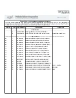
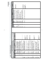
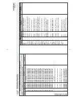
00A
AD 33 027C
85032#*SUP
P
LY
INJE
CT
INS
T
A
LL C46P
INSTALLA
T
IO
N
PA
RT
S
30015
00B
AD 33 027B
85032#* SUP
P
LY
INJE
CT
O
R
INSTAL C5P
INSTALLA
T
IO
N
PA
RT
S
30020 & 30022
00C
SA
33 059A
85032J*S
UPP
L
Y A
S
S
Y
=
C
6P+
C
5P+
C
4P
MAJ
O
R A
S
S
E
MB
LY
00D
SA
02 039D
91017# PIP
ING/5FLSHS
U
P=
30"UNI(
240V)
P
A
R
T
O
F
00C(
S
E
E
19,20,21)
00E
AV
W33001
81482B$P
RES
S
G
U
AG
E+
REG
U
LATOR A
S
S
Y
CM
PA
RT
O
F
00C(
S
E
E
22,23)
001
W2 03611
75392D* SUP
-CHUTE 5-F
L
US
H=
30"
C456M
00C (
W
ELDME
N
T
)
002
02 02646
87261C ENCLO
S
URE
=V
ALV
E
S
U
P INJ
.
00C
003
02 02664
87522C ENCLO
S
URE
=V
ALV
E
-L
OW
ER S
IDE
00C
004
02 02648
ENCLO
S
URE
-R
E
A
R=
SUP
P
LY
INJE
CT
O
R
00C
005
02 02701
87286B B
A
FF
LE
-C
O
NDENS
ATION=
SUP
INJ
00C
006
02 02647
ENCLO
S
URE
-F
RONT=S
UPP
L
Y INJ
E
CTOR
00C
007
27A017
1/2"P
IPE
STRAP
1HOLE
R.COND TB#1276
00C
008
SA
02 066
70297B*CO
V
E
R
AS
SY
=S
UPP
INJ
00C
009
02 03617
89406D PLA
T
E
=
S
U
PP
INJ MT-
F
RONT
00A,00B
010
02 03613
77361C PLA
T
E
-RE
AR MO
UNT
-S
UP
PINJ
-C
W
M
00A,00B
011
02 03612
92202B P
L
ATE=
COV
E
R S
U
PINJ
CWM
00A,00B
012
02 03615
78073A TUBE
=2+
1
/2ODX
062S/S
5"LG
00A,00B
(W
ELDE
D T
O
CYL.)
013
02 15773
86356B P
INCHVA
L
VE
T
U
B
E
-HYP
ALO
N
00A,00B
014
02 03427
83197A DRA
IN SUMP
CLAMP
PA
D
00A,00B
015
27A082
HOS
E
CLA
M
P,2+
9/16-
3.5"
CADS
CR HS-
4
8
00A,00B
016A
03 CL2X2
85027C 1/2 CO
NDUIT=
90DE
G
1.62X
1.75
00A
016B
03 CL2X5
85027# 1/2 CO
NDUIT 5X1.75
00B
017
03 01471
87371B P
L
ATE=
ADA
P
T T
O
3/8 OR 1/2FIT
00A,00B
018
12K040
1/2"
CO
ND.EMT CO
NDUIT PE
CO
#260B
00A,00B
019
02 02730
75832A NIP
P
LE
=S
UP INJ
215DEG
00D
020
02 02703
70089A NIP
P
LE
=S
UPINJ
180DEG
00D
021
96P011A
71
07Z
1/4"
2 WA
Y 240V
60 220V50
00D
022
SA
14 039
75627B$ P
R
ES
SG
AG
E,FLUSHS
UP 30+
36
00E
023
96J030D
1/2" P
R
ES
REG
U
LT
R S
E
T 28# F
E
M-
UNIO
N
00E
******** END O
F
P
A
RT
S LIS
T
********
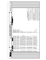
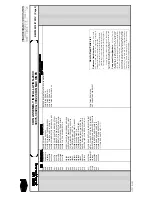
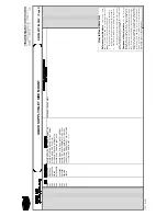
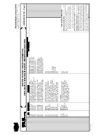
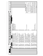
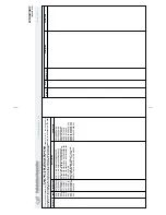
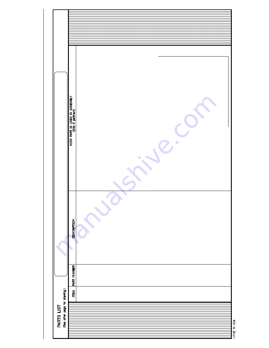
How to Read Parts List
Refe
re
nce
Item Numbers
—I
te
m
s
0
0
A
, 0
0
B
,
0
0
C
, etc.
, o
r 0
0
X,
00
Y, 0
0
Z
, etc.
, ap
pear
ing
at the
top
o
f
some
p
arts
lists,
are
fo
r
ref
eren
ce an
d
pr
ov
ide:
1
.
Th
e p
art
nu
mb
er
fo
r
the
entir
e as
sem
b
ly
d
epicted
in
th
e d
rawin
g
or
a
majo
r
sub
-as
sem
b
ly
th
ereo
f,
an
d/o
r
2.
The r
an
g
e of
m
ach
ine m
o
dels this drawing
ap
plies to.
If
mo
re than
o
n
e ref
eren
ce
item
ap
pear
s, this usu
ally
m
ean
s th
is d
rawin
g
app
lies to m
o
re than
on
e assem
b
ly (and
th
us to mo
re than
o
n
e ran
g
e of
m
achin
es).
Com
ponent Item Numbers
—
F
o
r a
n
y i
tem on
th
e
d
raw
in
g
(e.g.,
item
➀
), t
h
ere
may be
s
e
v
e
ral co
rr
e-
spo
n
d
ing
ite
m
s on
the
p
arts list (
e.g
.,
00
1A
, 00
1B
, 0
0
1
C
,
etc.
) which
ar
e
sim
ilar co
mp
on
ents o
n
d
iff
eren
t assemb
lies
.
“How Part I
s Used
I
n
Assem
b
ly” id
entifies which
co
m
p
o-
nen
ts app
ly to
yo
ur m
ach
ine, by
listing
either the m
achin
e
m
o
del, or the ref
erence item
nu
m
b
er
fr
o
m
th
e
to
p of
th
e
p
arts lis
t
(e
.g
.,
00
A, 0
0
B
, 0
0
C
, etc.
),
or
a par
ticular
char
ac-
ter
istic (e.
g
.,
b
ro
n
ze o
r stain
les
s steel),
or
sp
ecial o
rd
erin
g
inform
atio
n,
su
ch as
a r
ep
air
kit nu
m
b
er
.
BMP
92
00
19
/93
2
5
1
V
(P
a
ge
2)
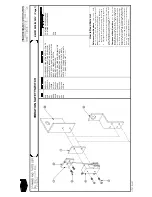
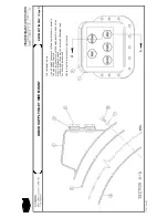
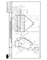
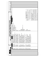
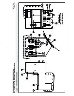
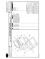
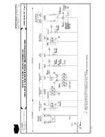
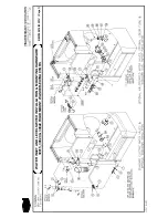
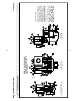
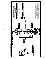
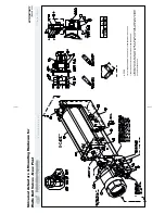
SUPPLY INJECTOR AND
INSTALLATION
30015,
30020 &
30022 RIGID MOUNT WASHER-EXTRACTORS
Summary of Contents for 30015
Page 6: ......
Page 8: ......
Page 10: ......
Page 19: ...Section 1 Service and Maintenance ...
Page 51: ...Section 2 Drive Assemblies ...
Page 59: ...BMP950003 95107V Page 1 MOTOR MOUNT 30015 30020 S4A S4G S4J S4T ...
Page 68: ......
Page 69: ...Section 3 Bearing Assemblies ...
Page 72: ...BMP910032 96141V Page 1 MAIN BEARING ASSEMBLY 30015C4x M4x K5x S5x ...
Page 74: ...BMP910033 96141V Page 1 MAIN BEARING ASSEMBLY ...
Page 76: ...BMP910034 95116V Page 1 MAIN BEARING ASSEMBLY 30015M6x ...
Page 80: ...BMP910035 93251V Page 1 JACKSHAFT ASSEMBLY 30015 30020 30022 RIGID MOUNT WASHER EXTRACTORS ...
Page 82: ......
Page 83: ...Section 4 Shell and Door Assemblies ...
Page 86: ...BMP920009 94491V Page 1 DOOR ASSEMBLY 30015 30020 RIGID MOUNT WASHER EXTRACTORS ...
Page 90: ......
Page 91: ...Section 5 Control and Sensing Devices ...
Page 100: ...BMP920010 97281V Page 1 COIN ASSEMBLY INSTALLATION 240V 30015 30020 30022 COIN MACHINES ...
Page 105: ...Section 6 Chemical Supply Devices ...
Page 113: ...Section 7 Water and Steam Piping and Assemblies ...
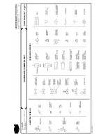
Page 114: ...ISOMETRIC SYMBOLS STANDARD SYMBOLS BMP920008 93027V Page 1 SCHEMATIC SYMBOLS KEY ...
Page 132: ...BMP920021 93251V Page 1 STEAM INSTALLATION 30015 30020 30022 RIGID MOUNT WASHER EXTRACTORS ...
Page 138: ...BMP920017 93251V Page 1 ELECTRIC DRAIN VALVE 30015 30020 30022 RIGID MOUNT WASHER EXTRACTORS ...