Ë
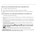
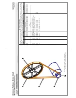
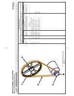
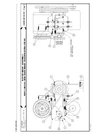
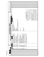
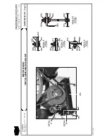
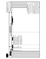
Main Drive and Centrifugal Switch Belt Pulleys For Single Motor Drive
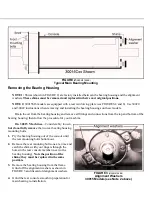
See FIGURE 5 during the following procedures:
1. Stretch a string from the motor pulley to the main drive pully as shown on FIGURE 5.
2. Adjust the position of the main drive pulley until the string touches A, B, C, and D. Secure the main drive
pully.
Ë
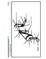
Extract, Main Drive, and Centrifugal Switch Belt Pulleys For Dual Motor Drive
See FIGURE 5 during the following procedures:
1. Stretch a string from the Extract Clutch on E2/Drain (large) motor to the pulley on the jackshaft as shown on
FIGURE 5.
2. Adjust the position of the jackshaft pulley until the string touches A, B, C, and D. Secure the jackshaft pulley.
3. Check the main drive pulley for alignment with the jackshaft pulley. Stretch a string from the jackshaft pulley
to the main drive pulley.
4. Adjust the main drive pulley position if necessary. Now check the centrifugal switch pulley (M4P, M5P,
M6P, and M7P models only) alignment.
CRUSH AND ENTANGLE HAZARD—Belts and pulleys can crush and entangle
body parts.
☞
Insure belt and pulley guards are in place before operating machine.
Ë
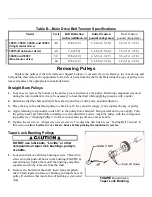
Testing Belt Alignment
—After aligning the belts, observe the belts with the machine operating. If an ad-
justment is necessary, lock OFF and tag out power before proceeding.
C
B
C
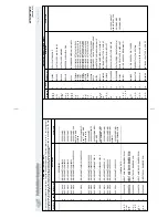
Summary of Contents for 30015
Page 6: ......
Page 8: ......
Page 10: ......
Page 19: ...Section 1 Service and Maintenance ...
Page 51: ...Section 2 Drive Assemblies ...
Page 59: ...BMP950003 95107V Page 1 MOTOR MOUNT 30015 30020 S4A S4G S4J S4T ...
Page 68: ......
Page 69: ...Section 3 Bearing Assemblies ...
Page 72: ...BMP910032 96141V Page 1 MAIN BEARING ASSEMBLY 30015C4x M4x K5x S5x ...
Page 74: ...BMP910033 96141V Page 1 MAIN BEARING ASSEMBLY ...
Page 76: ...BMP910034 95116V Page 1 MAIN BEARING ASSEMBLY 30015M6x ...
Page 80: ...BMP910035 93251V Page 1 JACKSHAFT ASSEMBLY 30015 30020 30022 RIGID MOUNT WASHER EXTRACTORS ...
Page 82: ......
Page 83: ...Section 4 Shell and Door Assemblies ...
Page 86: ...BMP920009 94491V Page 1 DOOR ASSEMBLY 30015 30020 RIGID MOUNT WASHER EXTRACTORS ...
Page 90: ......
Page 91: ...Section 5 Control and Sensing Devices ...
Page 100: ...BMP920010 97281V Page 1 COIN ASSEMBLY INSTALLATION 240V 30015 30020 30022 COIN MACHINES ...
Page 105: ...Section 6 Chemical Supply Devices ...
Page 113: ...Section 7 Water and Steam Piping and Assemblies ...
Page 114: ...ISOMETRIC SYMBOLS STANDARD SYMBOLS BMP920008 93027V Page 1 SCHEMATIC SYMBOLS KEY ...
Page 132: ...BMP920021 93251V Page 1 STEAM INSTALLATION 30015 30020 30022 RIGID MOUNT WASHER EXTRACTORS ...
Page 138: ...BMP920017 93251V Page 1 ELECTRIC DRAIN VALVE 30015 30020 30022 RIGID MOUNT WASHER EXTRACTORS ...


