

MSFD0501BE/9273AV (1 of 1)
È
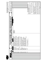
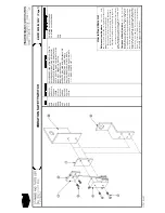
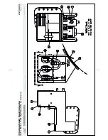
ABOUT THE COIN COUNTER
Ê
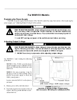
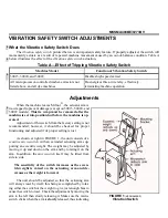
Description
NOTE: Ensure that the machine is level for proper
coin counter operation.
The coin counter can be adjusted to count from 1 to
63 coins without tools or extra parts (for further informa-
tion see “HOW TO SET REQUIRED NUMBER OF
COINS” in the “PROGRAMMING, OPERATING AND
TROUBLESHOOTING” manual). A coin depressing the
coin switch actuator (FIGURES 1 and 2) causes an input
to the microprocessor. Operation begins when the micro-
processor receives the correct number of inputs.
Each coin is analyzed as it passes through the coin
counter. Valid coins are counted, invalid coins are auto-
matically ejected or held in the rejector channel (the bent-
coin release returns the coin). The furnished U.S. coin
rejector (foreign coin rejectors optional) accepts quarters
only, smaller coins are rejected, and larger coins will not
fit in the slot.
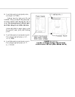
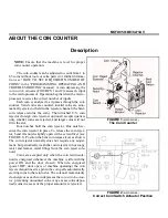
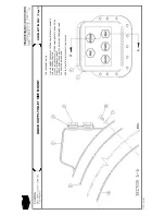
Four notches hold the coin rejector. One notch se-
cures the coin rejector in place. To release the coin rejec-
tor, bend this notch slightly open with a screwdriver (see
FIGURE 1). Position the bent coin release lever as shown.
The coin rejector normally does not require any adjust-
ment, but periodically wash the coin rejector in hot soapy
water and remove metal filings from the coin reject sole-
noid.
Coins are accepted only when the coin return sole-
noid is energized (whenever the machine is idle with the
power ON and the door closed). When de-energized
(power OFF, door open, or machine operating) the coin
reject solenoid inserts a pin in the coin path, automatically
ejecting coins to the return slot. The solenoid momentarily
de-energizes as each coin depresses the coin switch actua-
tor, preventing uncounted coins. Any excess coins depos-
ited (coins in excess of the proper amount) are rejected.
Ê
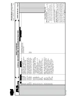
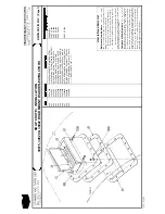
Troubleshooting
If the coin reject solenoid buzzes when energized,
dirt is preventing it from seating fully. If the coin counter
mechanism is rejecting all coins, the solenoid should be
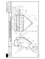
replaced. The coin switch is factory adjusted and does not
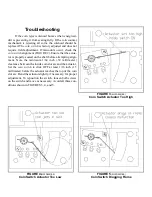
require field adjustment. If miscounts occur, check the
coin switch alignment (FIGURE 2). Ensure that the actua-
tor is properly seated on the shaft before attempting align-
ment. Note the minimum 1/64 inch (.39 millimeter)
clearance between the inside coin slot arc and the actuator.
Set the coin switch to click OFF at least 1/16 inch (1.5
millimeter) before the actuator reaches the top of the coin
slot arc. Bend the actuator slightly, if necessary, for proper
adjustment. To reposition the switch, loosen both screws
on the switch and move as necessary. Avoid all three con-
ditions shown in FIGURES 3, 4, and 5.
Î
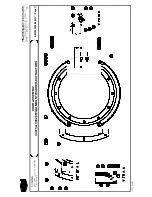
FIGURE 1
(MSFD0501BE)
Î
The Coin Counter
Î
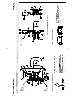
FIGURE 2
(MSFD0501BE)
Î
Correct Coin Switch Actuator Position
Î
FIGURE 3
(MSFD0501BE)
Î
Coin Switch Actuator Too High
Î
FIGURE 4
(MSFD0501BE)
Î
Coin Switch Actuator Too Low
Î
FIGURE 5
(MSFD0501BE)
Î
Coin Switch Dragging Frame
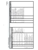
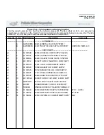
Summary of Contents for 30015
Page 6: ......
Page 8: ......
Page 10: ......
Page 19: ...Section 1 Service and Maintenance ...
Page 51: ...Section 2 Drive Assemblies ...
Page 59: ...BMP950003 95107V Page 1 MOTOR MOUNT 30015 30020 S4A S4G S4J S4T ...
Page 68: ......
Page 69: ...Section 3 Bearing Assemblies ...
Page 72: ...BMP910032 96141V Page 1 MAIN BEARING ASSEMBLY 30015C4x M4x K5x S5x ...
Page 74: ...BMP910033 96141V Page 1 MAIN BEARING ASSEMBLY ...
Page 76: ...BMP910034 95116V Page 1 MAIN BEARING ASSEMBLY 30015M6x ...
Page 80: ...BMP910035 93251V Page 1 JACKSHAFT ASSEMBLY 30015 30020 30022 RIGID MOUNT WASHER EXTRACTORS ...
Page 82: ......
Page 83: ...Section 4 Shell and Door Assemblies ...
Page 86: ...BMP920009 94491V Page 1 DOOR ASSEMBLY 30015 30020 RIGID MOUNT WASHER EXTRACTORS ...
Page 90: ......
Page 91: ...Section 5 Control and Sensing Devices ...
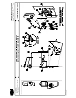
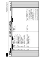
Page 100: ...BMP920010 97281V Page 1 COIN ASSEMBLY INSTALLATION 240V 30015 30020 30022 COIN MACHINES ...
Page 105: ...Section 6 Chemical Supply Devices ...
Page 113: ...Section 7 Water and Steam Piping and Assemblies ...
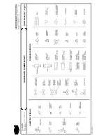
Page 114: ...ISOMETRIC SYMBOLS STANDARD SYMBOLS BMP920008 93027V Page 1 SCHEMATIC SYMBOLS KEY ...
Page 132: ...BMP920021 93251V Page 1 STEAM INSTALLATION 30015 30020 30022 RIGID MOUNT WASHER EXTRACTORS ...
Page 138: ...BMP920017 93251V Page 1 ELECTRIC DRAIN VALVE 30015 30020 30022 RIGID MOUNT WASHER EXTRACTORS ...


