


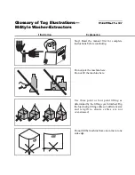

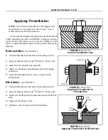

Illustration
Explanation
Illustration
Explanation
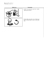
Install the appropriate part here before
operating the machine.
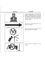
During drain and extract, the cylinder must
rotate counterclockwise when viewed from
here.
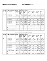
Do not strike shell front of washer-extractors
during fork lifting. Striking shell front will
cause door to leak.
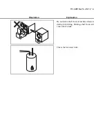
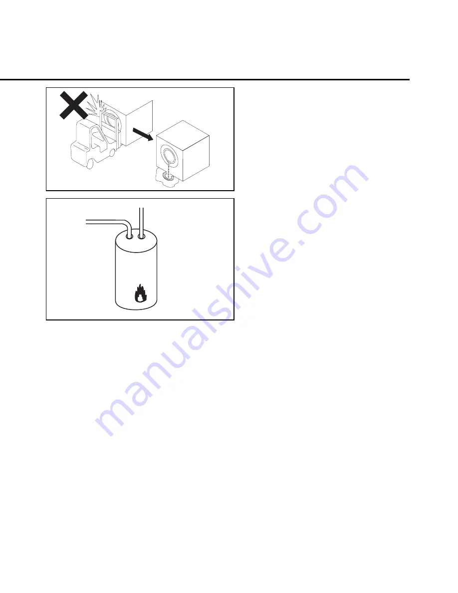
This is the hot water inlet.
7\_ccQbi _V DQW 9\\ecdbQdY_^c±
=Cdi\U GQcXUb5hdbQSd_bc
=C9EE=D715)$$)3F " "
Summary of Contents for 30015
Page 6: ......
Page 8: ......
Page 10: ......
Page 19: ...Section 1 Service and Maintenance ...
Page 51: ...Section 2 Drive Assemblies ...
Page 59: ...BMP950003 95107V Page 1 MOTOR MOUNT 30015 30020 S4A S4G S4J S4T ...
Page 68: ......
Page 69: ...Section 3 Bearing Assemblies ...
Page 72: ...BMP910032 96141V Page 1 MAIN BEARING ASSEMBLY 30015C4x M4x K5x S5x ...
Page 74: ...BMP910033 96141V Page 1 MAIN BEARING ASSEMBLY ...
Page 76: ...BMP910034 95116V Page 1 MAIN BEARING ASSEMBLY 30015M6x ...
Page 80: ...BMP910035 93251V Page 1 JACKSHAFT ASSEMBLY 30015 30020 30022 RIGID MOUNT WASHER EXTRACTORS ...
Page 82: ......
Page 83: ...Section 4 Shell and Door Assemblies ...
Page 86: ...BMP920009 94491V Page 1 DOOR ASSEMBLY 30015 30020 RIGID MOUNT WASHER EXTRACTORS ...
Page 90: ......
Page 91: ...Section 5 Control and Sensing Devices ...
Page 100: ...BMP920010 97281V Page 1 COIN ASSEMBLY INSTALLATION 240V 30015 30020 30022 COIN MACHINES ...
Page 105: ...Section 6 Chemical Supply Devices ...
Page 113: ...Section 7 Water and Steam Piping and Assemblies ...
Page 114: ...ISOMETRIC SYMBOLS STANDARD SYMBOLS BMP920008 93027V Page 1 SCHEMATIC SYMBOLS KEY ...
Page 132: ...BMP920021 93251V Page 1 STEAM INSTALLATION 30015 30020 30022 RIGID MOUNT WASHER EXTRACTORS ...
Page 138: ...BMP920017 93251V Page 1 ELECTRIC DRAIN VALVE 30015 30020 30022 RIGID MOUNT WASHER EXTRACTORS ...


