R
Pellerin
Milnor
Corporation
Pellerin
Milnor
Corporation
P.
O.
Box
400,
Kenner
,L
A
70063-0400
Litho
in
U.S.A.
BMP920025/92662V
(1
of
2)
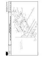
BMP920025/92662V
(Sheet
1
of
2)
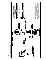
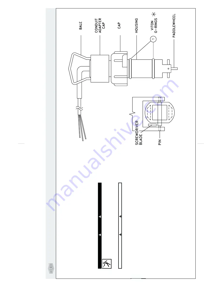
P
a
d
dlew
heel
F
lo
w
Sensor
Identification
and
Description
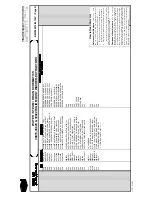
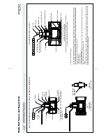
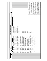
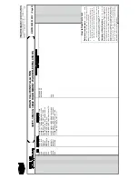
The
flow
sensor
is
installed
in
a
pipe
line
to
measure
flow
rate.
The
flow
passing
by
the
flow
sensor
paddlewheel
rotates
the
paddlewheel,
moving
the
magnets
past
a
coil
in
the
transducer
body.
An
AC
voltage
is
induced
in
the
coil
by
the
rotating
magnets
of
the
paddlewheel.
Both
frequency
and
amplitude
of
the
output
of
the
coil
are
directly
proportional
to
the
velocity
of
the
fluid
flow
in
the
pipe.
A
complete
cycle
occurs
every
time
two
of
the
paddlewheel
blades
go
by
the
coil;
therefore,
two
entire
cycles
are
generated
for
each
paddlewheel
rotation.
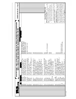
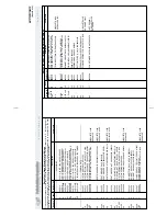
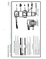
Safety
Instructions
Lock
OFF
and
tag
out
power
to
machine
at
wall
disconnect.
Power
switches
on
machine
and
control
box
disable
only
control
circuit
power
in
electrical
boxes.
D
ANGER
SHOCK
HAZARD
will
cause
death
or
severe
injury
.
+
CA
UTION
+
Turn
off
fluids
before
removing
flow
sensor
from
pipe
line.
+
Maintenance
1 2 3
.
Paddlewheel
must
turn
freely,
if
not,
see
troubleshooting
below.
.
Inspect
flow
sensor
electrical
connections
and
cable.
.
Check
O-rings
and
lubricate
with
G.E.
Silcone
Compound
G660
or
similar.
Keep
paddlewheel
and
pin
free
of
lubrication
(replacement
paddlewheels
and
other
parts
are
available
from
manufactuer).
Troubleshooting
The
flow
sensor
requires
minimal
care.
Check
your
flow
sensor
every
three
months
until
actual
maintenance
intervals
can
be
determined.
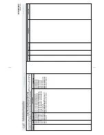
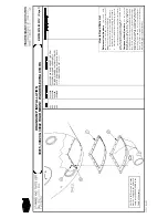
After
removing
flow
sensor:
1
2
3
.Remove
the
flow
sensor
from
the
pipe
and
insert
the
plug
into
the
pipe
fitting.
Clean
any
external
debris
from
the
paddlewheel.
.
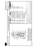
Using
a
small
flat-bladed
screwdriver,
gently
pry
one
of
the
paddlewheel
mounting
ears
away
from
the
pin
(see
FIGURE
2).
.
When
one
end
of
the
pin
is
free,
gently
work
the
paddlewheel
and
pin
out
of
the
remaining
mount-
ing
ear.
4.
Throughly
clean
the
pin,
paddle,
and
pin
holes
with
a
wire
brush
and/or
toothpick
along
with
al-
cohol
and/or
soap
and
water.
5.
To
reinstall
the
paddlewheel
and
pin,
reverse
steps
1,
2,
and
3.
6.
After
cleaning,
the
paddlewheel
should
spin
freely
without
binding
or
sticking.
The
paddlewheel
is
designed
to
rotate
on
the
shaft;
the
shaft
should
not
rotate
with
respect
to
the
housing.
The
paddlewheel
must
turn
freely.
If
it
does
not,
clean
the
paddlewheel
assembly
as
follows:
FIGURE
2:
REMO
V
A
L
O
F
PADDLEWHEEL
PIN
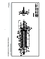
FIGURE
1:
FL
O
W
SENSOR
F
Summary of Contents for 30015
Page 6: ......
Page 8: ......
Page 10: ......
Page 19: ...Section 1 Service and Maintenance ...
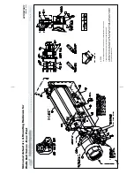
Page 51: ...Section 2 Drive Assemblies ...
Page 59: ...BMP950003 95107V Page 1 MOTOR MOUNT 30015 30020 S4A S4G S4J S4T ...
Page 68: ......
Page 69: ...Section 3 Bearing Assemblies ...
Page 72: ...BMP910032 96141V Page 1 MAIN BEARING ASSEMBLY 30015C4x M4x K5x S5x ...
Page 74: ...BMP910033 96141V Page 1 MAIN BEARING ASSEMBLY ...
Page 76: ...BMP910034 95116V Page 1 MAIN BEARING ASSEMBLY 30015M6x ...
Page 80: ...BMP910035 93251V Page 1 JACKSHAFT ASSEMBLY 30015 30020 30022 RIGID MOUNT WASHER EXTRACTORS ...
Page 82: ......
Page 83: ...Section 4 Shell and Door Assemblies ...
Page 86: ...BMP920009 94491V Page 1 DOOR ASSEMBLY 30015 30020 RIGID MOUNT WASHER EXTRACTORS ...
Page 90: ......
Page 91: ...Section 5 Control and Sensing Devices ...
Page 100: ...BMP920010 97281V Page 1 COIN ASSEMBLY INSTALLATION 240V 30015 30020 30022 COIN MACHINES ...
Page 105: ...Section 6 Chemical Supply Devices ...
Page 113: ...Section 7 Water and Steam Piping and Assemblies ...
Page 114: ...ISOMETRIC SYMBOLS STANDARD SYMBOLS BMP920008 93027V Page 1 SCHEMATIC SYMBOLS KEY ...
Page 132: ...BMP920021 93251V Page 1 STEAM INSTALLATION 30015 30020 30022 RIGID MOUNT WASHER EXTRACTORS ...
Page 138: ...BMP920017 93251V Page 1 ELECTRIC DRAIN VALVE 30015 30020 30022 RIGID MOUNT WASHER EXTRACTORS ...


