


Ê
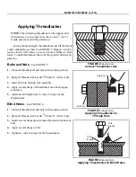
Applying Threadlocker
NOTE: The following threadlocker information and
illustrations are excerpts from the Loctite
®
User’s
Guide and are used with permission.
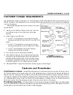
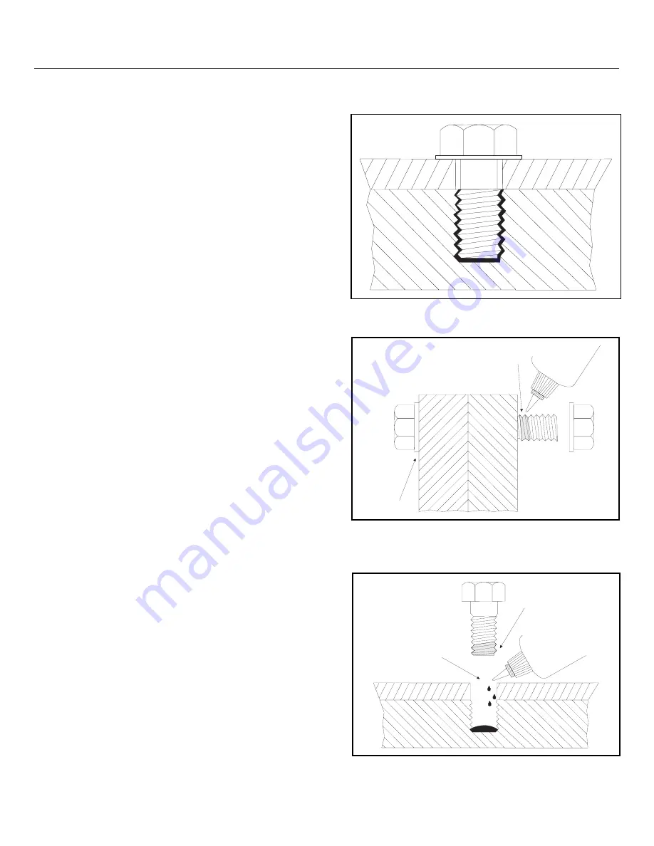
For maximum strength, threadlocker must fill the thread
voids completely, as shown in FIGURE 2. Organic or petro-
leum solvent will remove excess uncured adhesive from
joints. Consult information below for the specific fastener ap-
plication.
Ë
Bolts and Nuts
—See FIGURE 3.
1. Clean all threads (bolt and nut) with cleaning solvent.
2. Spray all threads with Loctite
®
Primer N. Allow to dry.
3. Insert bolt into through hole assembly.
4. Apply several drops of threadlocker onto bolt engage-
ment area.
5. Assemble and tighten nut to correct torque for the
threadlocker.
Ë
Blind Holes
—See FIGURE 4.
1. Clean all threads (bolt and nut) with cleaning solvent.
2. Spray all threads with Loctite
®
Primer N. Allow to dry.
3. Squirt several drops down female threads into bottom of
hole.
4. Apply several drops to bolt.
5. Tighten to correct torque for the threadlocker.
Î
FIGURE 2
(MSSM0101CE)
Î
Correct Threadlocker Use
Apply here
Not here
Î
FIGURE 3
(MSSM0101CE)
Î
Applying Threadlocker to
Through Hole
Onto
threads
Onto
threads
Î
FIGURE 4
(MSSM0101CE)
Î
Applying Threadlocker to Blind Holes
MSSM0101CE/9906AV (2 of 19)
Summary of Contents for 30015
Page 6: ......
Page 8: ......
Page 10: ......
Page 19: ...Section 1 Service and Maintenance ...
Page 51: ...Section 2 Drive Assemblies ...
Page 59: ...BMP950003 95107V Page 1 MOTOR MOUNT 30015 30020 S4A S4G S4J S4T ...
Page 68: ......
Page 69: ...Section 3 Bearing Assemblies ...
Page 72: ...BMP910032 96141V Page 1 MAIN BEARING ASSEMBLY 30015C4x M4x K5x S5x ...
Page 74: ...BMP910033 96141V Page 1 MAIN BEARING ASSEMBLY ...
Page 76: ...BMP910034 95116V Page 1 MAIN BEARING ASSEMBLY 30015M6x ...
Page 80: ...BMP910035 93251V Page 1 JACKSHAFT ASSEMBLY 30015 30020 30022 RIGID MOUNT WASHER EXTRACTORS ...
Page 82: ......
Page 83: ...Section 4 Shell and Door Assemblies ...
Page 86: ...BMP920009 94491V Page 1 DOOR ASSEMBLY 30015 30020 RIGID MOUNT WASHER EXTRACTORS ...
Page 90: ......
Page 91: ...Section 5 Control and Sensing Devices ...
Page 100: ...BMP920010 97281V Page 1 COIN ASSEMBLY INSTALLATION 240V 30015 30020 30022 COIN MACHINES ...
Page 105: ...Section 6 Chemical Supply Devices ...
Page 113: ...Section 7 Water and Steam Piping and Assemblies ...
Page 114: ...ISOMETRIC SYMBOLS STANDARD SYMBOLS BMP920008 93027V Page 1 SCHEMATIC SYMBOLS KEY ...
Page 132: ...BMP920021 93251V Page 1 STEAM INSTALLATION 30015 30020 30022 RIGID MOUNT WASHER EXTRACTORS ...
Page 138: ...BMP920017 93251V Page 1 ELECTRIC DRAIN VALVE 30015 30020 30022 RIGID MOUNT WASHER EXTRACTORS ...


