

Ê
For MARK II Models
Ë
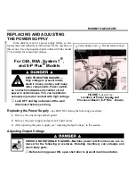
Replacing the Power Supply
The Mark II power supply mounts inside of the Mark II control box atop the machine. After replacing the
power supply, see “Adjusting Output Voltage” in this section.
ELECTROCUTION HAZARD—High voltage is present inside electric boxes, mo-
tors, and many other components. Power switches on machine disable only
control circuit power in certain boxes. You can be killed or seriously injured on
contact with high voltage.
☞
Lock OFF and tag out power at the wall disconnect before servicing.
Ë
Adjusting Output Voltage
ELECTROCUTION HAZARD—High voltage is present inside electrical box dur-
ing the following procedure. You can be killed or seriously injured by contact
with exposed components which are energized at 120VAC or higher.
☞
DO NOT touch any components while adjusting output voltage.
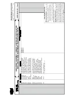
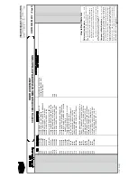
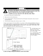
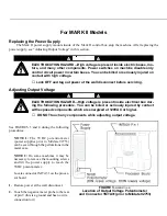
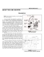
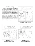
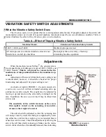
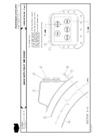
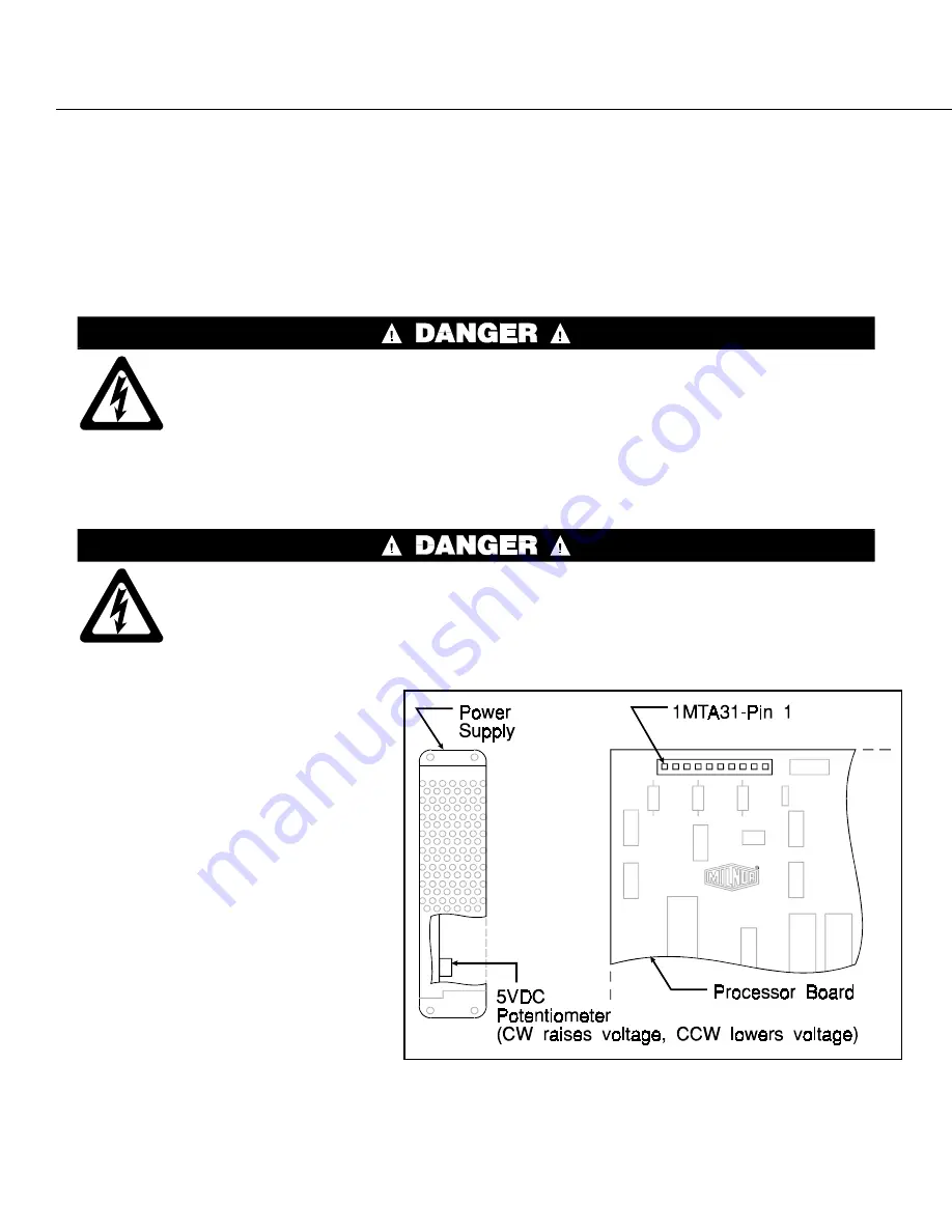
See FIGURES 3 and 4 during the following
procedures:
N O T E 1 : The 5VDC potentiometer
(power supplies prior to Mildate 92753)
can be seen through the perforations in the
metal case.
NOTE 2: On some machines it may be
necessary to remove the mounting screws
and tilt the power supply to reach the
5VDC potentiometer.
Locate connector 1MTA31 on the proces-
sor board.
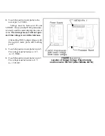
1. Restore power at the wall disconnect.
2. Touch the negative meter probe to the rear
of pin 9 (this is a ground and has no wire
connection to it).
2. Touch the positive meter probe to the
rear of pin 3 (+5VDC).
Voltage must be between 4.95 and
5.06VDC. If not, turn the 5VDC potentiome-
ter slowly until the meter displays the correct
value. The microprocessor will not oper-
ate if this voltage is not within tolerance.
After setting 5VDC output voltage, (with
the negative meter probe still touching
pin 9):
1. Touch the positive meter probe to pin 5.
The voltage must be b11.5
to +13.5VDC.
2. Touch the positive meter probe to pin 7.
The voltage must be between -11.5
to - 13.5VDC.
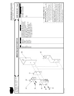
Î
FIGURE 3
(MSSM0711AE)
Î
Location of Output Voltage Potentiometer
and Connector 1MTA31(prior to Mildate 92753)
Î
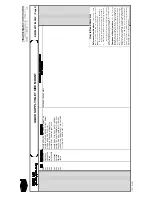
FIGURE 4
(MSSM0711AE)
Î
Location of Output Voltage Potentiometer
and Connector 1MTA31 (After Mildate 92753)
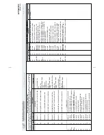
Summary of Contents for 30015
Page 6: ......
Page 8: ......
Page 10: ......
Page 19: ...Section 1 Service and Maintenance ...
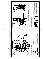
Page 51: ...Section 2 Drive Assemblies ...
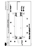
Page 59: ...BMP950003 95107V Page 1 MOTOR MOUNT 30015 30020 S4A S4G S4J S4T ...
Page 68: ......
Page 69: ...Section 3 Bearing Assemblies ...
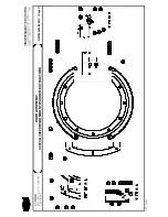
Page 72: ...BMP910032 96141V Page 1 MAIN BEARING ASSEMBLY 30015C4x M4x K5x S5x ...
Page 74: ...BMP910033 96141V Page 1 MAIN BEARING ASSEMBLY ...
Page 76: ...BMP910034 95116V Page 1 MAIN BEARING ASSEMBLY 30015M6x ...
Page 80: ...BMP910035 93251V Page 1 JACKSHAFT ASSEMBLY 30015 30020 30022 RIGID MOUNT WASHER EXTRACTORS ...
Page 82: ......
Page 83: ...Section 4 Shell and Door Assemblies ...
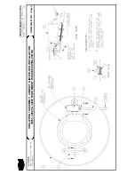
Page 86: ...BMP920009 94491V Page 1 DOOR ASSEMBLY 30015 30020 RIGID MOUNT WASHER EXTRACTORS ...
Page 90: ......
Page 91: ...Section 5 Control and Sensing Devices ...
Page 100: ...BMP920010 97281V Page 1 COIN ASSEMBLY INSTALLATION 240V 30015 30020 30022 COIN MACHINES ...
Page 105: ...Section 6 Chemical Supply Devices ...
Page 113: ...Section 7 Water and Steam Piping and Assemblies ...
Page 114: ...ISOMETRIC SYMBOLS STANDARD SYMBOLS BMP920008 93027V Page 1 SCHEMATIC SYMBOLS KEY ...
Page 132: ...BMP920021 93251V Page 1 STEAM INSTALLATION 30015 30020 30022 RIGID MOUNT WASHER EXTRACTORS ...
Page 138: ...BMP920017 93251V Page 1 ELECTRIC DRAIN VALVE 30015 30020 30022 RIGID MOUNT WASHER EXTRACTORS ...


