


- 46 -
Description of Ready Menu,
Continued
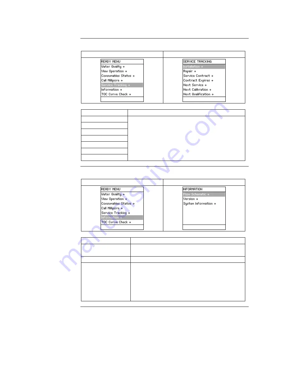
Service
Tracking
Diagram 1
Diagram 2
Item Description
Installation
Repair
Service Contract
Contract Expires
Next Service
Next Calibration
Next Qualification
View information that was inputted into the System
at time of servicing.
View information related to upcoming service.
NOTE:
This information is entered by a Millipore
Representative.
Information
Diagram 1
Diagram 2
Item Description
Flow Schematic
View information that explains the purpose of the
major components.
Version
View Software versions.
System Information
View:
•
System Type,
•
Catalogue Number,
•
Serial Number,
•
Installation Date, and
•
Manufacturing Date.
Summary of Contents for milli-q
Page 1: ...User Manual Milli Q Reference System...
Page 36: ...36 Software Map M a p...


