background image

OM-244 997 Page 1

SECTION 1 

 SAFETY PRECAUTIONS - READ BEFORE USING

som _2009

08

7

Protect yourself and others from injury — read and follow these precautions.

1-1. Symbol Usage

DANGER! 

 Indicates a hazardous situation which, if

not avoided, will result in death or serious injury. The

possible hazards are shown in the adjoining symbols

or explained in the text.

Indicates a hazardous situation which, if not avoided,

could result in death or serious injury. The possible

hazards are shown in the adjoining symbols or ex-

plained in the text.

NOTICE


 Indicates statements not related to personal injury.

.

Indicates special instructions.

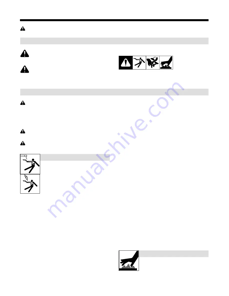
This group of symbols means Warning! Watch Out! ELECTRIC

SHOCK, MOVING PARTS, and HOT PARTS hazards. Consult sym-

bols and related instructions below for necessary actions to avoid the

hazards.

1-2. Arc Welding Hazards

The symbols shown below are used throughout this manual

to call attention to and identify possible hazards. When you

see the symbol, watch out, and follow the related instructions

to avoid the hazard. The safety information given below is

only a summary of the more complete safety information

found in the Safety Standards listed in Section 1-5. Read and

follow all Safety Standards.

Only qualified persons should install, operate, maintain, and

repair this unit.

During operation, keep everybody, especially children, away.

ELECTRIC SHOCK can kill.

Touching live electrical parts can cause fatal shocks

or  severe burns. The electrode and work circuit is

electrically live whenever the output is on. The input

power circuit and machine internal circuits are also

live when power is on. In semiautomatic or automatic

wire welding, the wire, wire reel, drive roll housing,

and all metal parts touching the welding wire are

electrically live. Incorrectly installed or improperly

grounded equipment is a hazard.

D

Do not touch live electrical parts.

D

Wear dry, hole-free insulating gloves and body protection.

D

Insulate yourself from work and ground using dry insulating mats

or covers big enough to prevent any physical contact with the work

or ground.

D

Do not use AC output in damp areas, if movement is confined, or if

there is a danger of falling.

D

Use AC output ONLY if required for the welding process.

D

If AC output is required, use remote output control if present on

unit.

D

Additional safety precautions are required when any of the follow-

ing electrically hazardous conditions are present: in damp

locations or while wearing wet clothing; on metal structures such

as floors, gratings, or scaffolds; when in cramped positions such

as sitting, kneeling, or lying; or when there is a high risk of unavoid-

able or accidental contact with the workpiece or ground. For these

conditions, use the following equipment in order presented: 1) a

semiautomatic DC constant voltage (wire) welder, 2) a DC manual

(stick) welder, or 3) an AC welder with reduced open-circuit volt-

age. In most situations, use of a DC, constant voltage wire welder

is recommended. And, do not work alone!

D

Disconnect input power or stop engine before installing or

servicing this equipment. Lockout/tagout input power according to

OSHA 29 CFR 1910.147 (see Safety Standards).

D

Properly install and ground this equipment according to its

Owner’s Manual and national, state, and local codes.

D

Always verify the supply ground 

 check and be sure that input

power cord ground wire is properly connected to ground terminal in

disconnect box or that cord plug is connected to a properly

grounded receptacle outlet.

D

When making input connections, attach proper grounding conduc-

tor first 

 double-check connections.

D

Keep cords dry, free of oil and grease, and protected from hot metal

and sparks.

D

Frequently inspect input power cord for damage or bare wiring 

replace cord immediately if damaged 

 bare wiring can kill.

D

Turn off all equipment when not in use.

D

Do not use worn, damaged, undersized, or poorly spliced cables.

D

Do not drape cables over your body.

D

If earth grounding of the workpiece is required, ground it directly

with a separate cable.

D

Do not touch electrode if you are in contact with the work, ground,

or another electrode from a different machine.

D

Do not touch electrode holders connected to two welding ma-

chines at the same time since double open-circuit voltage will be

present.

D

Use only well-maintained equipment. Repair or replace damaged

parts at once. Maintain unit according to manual.

D

Wear a safety harness if working above floor level.

D

Keep all panels and covers securely in place.

D

Clamp work cable with good metal-to-metal contact to workpiece

or worktable as near the weld as practical.

D

Insulate work clamp when not connected to workpiece to prevent

contact with any metal object.

D

Do not connect more than one electrode or work cable to any

single weld output terminal.

SIGNIFICANT DC VOLTAGE exists in inverter weld-

ing power sources AFTER removal of inputpower.

D

Turn Off inverter, disconnect input power, and discharge input

capacitors according to instructions in Maintenance Section

before touching any parts.

HOT PARTS can burn.

D

Do not touch hot parts bare handed.

D

Allow cooling period before working on equip-

ment.

D

To handle hot parts, use proper tools and/or

wear heavy, insulated welding gloves and

clothing to prevent burns.

Summary of Contents for ArcStation

Page 1: ...ArcStation OM 244 997 A 2009 09 Visit our website at www MillerWelds com Place serial number or lot code sticker here...

Page 2: ...tinue the tradition They re just as committed to providing equipment and service that meets the high standards of quality and value established in 1929 This Owner s Manual is designed to help you get...

Page 3: ...es aux CEM 9 SECTION 3 WELDING TABLE SAFETY PRECAUTIONS READ BEFORE USING 11 3 1 Symbol Usage 11 3 2 Welding Table Hazards 11 SECTION 4 ASSEMBLY 13 4 1 30S And 30SX Welding Table Specifications 13 4 2...

Page 4: ......

Page 5: ...lds when in cramped positions such as sitting kneeling or lying or when there is a high risk of unavoid able or accidental contact with the workpiece or ground For these conditions use the following e...

Page 6: ...less they are properly prepared according to AWS F4 1 see Safety Standards D Do not weld where the atmosphere may contain flammable dust gas or liquid vapors such as gasoline D Connect work cable to t...

Page 7: ...panels covers and guards closed and securely in place D Have only qualified persons remove doors panels covers or guards for maintenance and troubleshooting as necessary D Reinstall doors panels cover...

Page 8: ...ther Hot Work NFPA Standard 51B from National Fire Protection Association Quincy MA 02269 phone 1 800 344 3555 website www nfpa org OSHA Occupational Safety and Health Standards for General Indus try...

Page 9: ...source lectrique courant lectrique s av re n cessaire se servir de la fonction de t l commande si l appareil en est quip D D autres consignes de s curit sont n cessaires dans les condi tions suivante...

Page 10: ...u laine et des bottes de protection LE SOUDAGE peut provoquer un incendie ou une explosion Le soudage effectu sur des conteneurs ferm s tels que des r servoirs tambours ou des conduites peut provoquer...

Page 11: ...lt rieur D Utiliser les quipements corrects les bonnes proc dures et suffi samment de personnes pour soulever et d placer les bouteilles D Lire et suivre les instructions sur les bouteilles de gaz com...

Page 12: ...intenir soigneusement ferm s les portes et les panneaux des sources de haute fr quence maintenir les clateurs une distan ce correcte et utiliser une terre et un blindage pour r duire les interf rences...

Page 13: ...r gion 5 Chicago est 312 353 2220 site Internet www osha gov U S Consumer Product Safety Commission CPSC 4330 East West Highway Bethesda MD 20814 t l phone 301 504 7923 site inter net www cpsc gov Ap...

Page 14: ...OM 244 997 Page 10...

Page 15: ...y D Before each use inspect the weld table for damage and verify it is secure and installed properly ELECTRIC SHOCK can kill Touching live electrical parts can cause fatal shocks or severe burns D Inc...

Page 16: ......

Page 17: ...n thick 1 or 300 607 Top X pattern 3 8 in thick 1 2 244 936 Subframe end 2 3 244 965 Foot mtg 4 4 244 949 Front Rear Rail 2 5 244 950 Tray bottom 1 6 245 618 Bracket stiffener 1 7 245 672 Cap tube sma...

Page 18: ...Top Use four bolts DD and four washers WW Install bolts into table top ends Use four bolts CC and four washers WW Install bolts into slotted holes for the end subframes and rails 3 8 in Thick Top Use...

Page 19: ...If the welding table has a solid top and an optional tool chest proceed to Subsection H If the welding table has an X pattern top and an optional tool chest proceed to Subsection G If the welding tab...

Page 20: ...e that rails are pushed in as close to gether as possible Do not tighten bolts at this time Do not install dust tray at this time Proceed to Subsection I CC Tools Needed 1 hex bit 3 16 in H Installing...

Page 21: ...t tray rails or Side View just AA for tool chest brackets AA and ZZ for dust tray rails or just AA for tool chest brackets J Installing Bottom Tray Use two people to rotate welding table It is recomme...

Page 22: ...ghten jam nuts on feet at this time Tools Needed 1 Welding table shown with optional X pattern top and tool chest L Installing Dust Tray And Tube Caps 1 Dust Tray Install dust tray into rail slides as...

Page 23: ...Attach work lead tab with one bolt DD to bottom side and at the rear of the top using either one of the two tapped holes Tools Needed 1 1 2 in hex bit 3 16 in EE and ZZ EE and ZZ 2 2 Top View Rear 3...

Page 24: ...in thick 1 or 300 606 Top solid 3 8 in thick 1 or 300 607 Top X pattern 3 8 in thick 1 2 244 936 Subframe end 2 3 244 965 Foot mtg 6 4 244 935 Subframe center 1 5 244 949 Front Rear Rail 4 6 244 950 T...

Page 25: ...eck the following instructions to be sure how tops will be positioned after assembly Use a mallet to tap tops together so they touch at the center 1 Four holes must be together in center of tops Tools...

Page 26: ...nds Use eight bolts CC and eight washers WW Install bolts into slotted holes for the center and end subframes and rails 3 8 in Thick Top Use eight bolts CC and eight washers WW Install bolts into tabl...

Page 27: ...n leveling feet at this time Tools Needed 1 2 2 AA and ZZ 1 2 in hex bit 3 16 in 3 Attention If the welding table has two solid tops and no optional tool chest proceed to Subsection J If the welding t...

Page 28: ...to Subsection J If optional tool chest is being installed proceed to Subsection H Tools Needed 1 2 in hex bit 3 16 in AA and ZZ AA and ZZ AA and ZZ Side View 1 G Installing Dust tray Rails To Optiona...

Page 29: ...in I Installing Tool Chest To Welding Table Use four bolts AA and four locknuts ZZ for dust tray rails or just four bolts AA for tool chest brackets and install tool chest assembly to the welding tab...

Page 30: ...ubframe Tighten all bolts and locknuts Do not install dust tray at this time Tools Needed 1 2 in hex bit 3 16 in AA and ZZ EE and ZZ AA and ZZ Welding table shown with optional tool chest K Leveling T...

Page 31: ...n and lift front of tray up Place flange on rear of tray behind angle iron support Lower front of tray until approximatelylevel Slide tray into position 2 Large Tube Cap 3 Small Tube Cap Push in a sma...

Page 32: ...end subframes 2 Tapped Holes For Work Lead Tab 3 Work Lead Tab Attach work lead tab with one bolt DD to bottom side and at the rear of the tops using any one of the four tapped holes Tools Needed 1 1...

Page 33: ...h the tool chest and install dust tray rails to top of tool chest Be sure that rails are pushed in as close together as possible Do not tighten bolts at this time Do not install dust tray at this time...

Page 34: ...e tool chest and install brackets to top of tool chest Be sure that brackets are pushed in as close together as possible Raise tool chest bracket assembly into position brackets should be to inside of...

Page 35: ...dust tray rails are on the inside of the subframe assemblies Tighten all bolts and locknuts 2 Dust Tray Install dust tray into rail slides as follows Tilt rear of tray down and lift front of tray up P...

Page 36: ...Optional Vise Mount Install and secure vise to the vise mount using the supplied hardware Remove tube cap from end subframe tube Insert vise mount into end subframe tube and secure with supplied bolt...

Page 37: ...vise on top of plate and mark hole locations Drill appropriate sized holes in plate for customer supplied mounting hardware When vise mount is removed to install vise place both vise mount and vise o...

Page 38: ...e Tools Needed 1 2 7 16 in hex bit 1 3 2 5 32 3 16 in 5 7 Installing Convenience Kit Gun Holder 1 Optional Gun Holder Gun holder will mount to any hole in the subframe except the top hole If installin...

Page 39: ...nd locknuts ZZ to secure tool tray to subframe Tools Needed hex bit 3 16 in 1 2 in 1 EE and ZZ 5 9 Installing Convenience Kit Clamp Bar 1 Optional Clamp Bar 2 Mounting Hole Selection Select the desire...

Page 40: ...Notes...

Page 41: ...Notes Work like a Pro Pros weld and cut safely Read the safety rules at the beginning of this manual...

Page 42: ...Notes FILLET GROOVE WELD JOINT TYPES BUTT BUTT BUTT BUTT T JOINT T JOINT T JOINT T JOINT FLAT VERTICAL HORIZONTAL OVERHEAD WELD POSITION Ref AWS ANSI D1 1 1G 1F 2G 2F 3G 3F 4G 4F Ref 804 248 A...

Page 43: ...and Subarc SAW Guns Induction Heating Coils and Blankets Cables and Non Electronic Controls APT SAF Model Plasma Cutting Torches Remote Controls Accessory Kits Replacement Parts No labor Spoolmate Sp...

Page 44: ...your personal records Always provide Model Name and Serial Style Number Contact a DISTRIBUTOR or SERVICE AGENCY near you Welding Supplies and Consumables Options and Accessories Personal Safety Equip...

Reviews: