background image


21

5. 

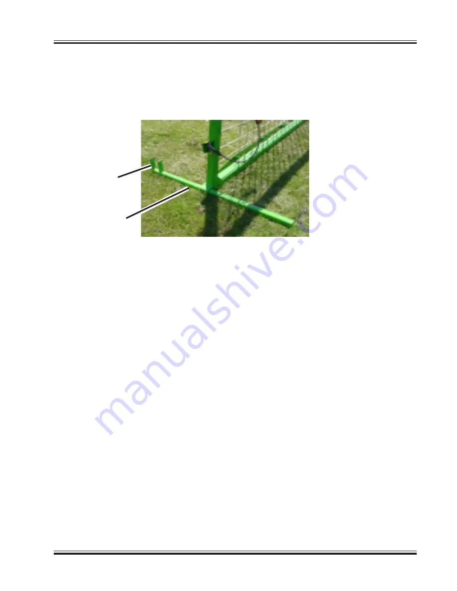
Reassemble the bolt and nut into the support feet tabs.  Remove the support feet from the 
pockets in the tunnel.  Insert the support feet into the pockets on the backstop with the tabs to 
the rear of the backstop.  The feet will help hold the backstop in the upright position.

NOTE:

 After two loads are placed in the bag, remove the feet from the backstop and continue bag-

ging.

6. 

Pull the bagger forward, giving yourself plenty of room to move the wheels and to install the 
bag onto the tunnel.

Support Feet 

In Backstop 

Pockets

Tabs

Summary of Contents for Ag-Bag G6170

Page 1: ...ANZ INC P O BOX 127 ST NAZIANZ WI 54232 920 773 2121 FAX 920 773 1200 OPERATOR S MANUAL DO NOT OPERATE THIS EQUIPMENT UNTIL THIS MANUAL HAS BEEN READ AND UNDERSTOOD Part Number 42 0901734C February 20...

Page 2: ...void the warranty MACHINE SERIAL NUMBER The machine serial number is located on the rear frame next to the bag boom tube For your convenience refer to this number and your product model number when re...

Page 3: ...ch To Bagging Position 22 Hook Tractor To Tow Hitch 26 Assemble PTO Shaft To Bagger and Tractor 26 Connect The Inoculant Applicator Units so equipped 28 Bag Identification 28 Bag Installation 29 Seal...

Page 4: ...l Bearings 66 Rotor Drive Chain 67 Hydraulic Pump Drive Chain 67 Gearbox Output Shaft Coupler Chain 68 Conveyor Drive Chain 69 Conveyor Drive Coupler Chain 70 Hydraulic Oil 71 Hydraulic Oil Filter 74...

Page 5: ...3 This Page Intentionally Left Blank...

Page 6: ...very and Delivery Check Lists customer and dealer copies follow this page Customer copies can remain with this manual Dealer copies can be removed along perforation and remain with dealer Ag Bagger Ch...

Page 7: ...ositions All chains are properly tightened Conveyor drive and driven chain Rotor drive chain Hydraulic pump drive chain All drive driven sprockets aligned properly Conveyor drive chain sprockets Rotor...

Page 8: ...ion in the owner s manual Explain and review with the customer the controls and safety equipment on the Bagger Explain that regular lubrication and proper adjustments are required for continued proper...

Page 9: ...positions All chains are properly tightened Conveyor drive and driven chain Rotor drive chain Hydraulic pump drive chain All drive driven sprockets aligned properly Conveyor drive chain sprockets Roto...

Page 10: ...tion in the owner s manual Explain and review with the customer the controls and safety equipment on the Bagger Explain that regular lubrication and proper adjustments are required for continued prope...

Page 11: ...n MAKE SURE that every individual who operates or works with this equip ment whether family member or employee is familiar with these safety precautions Miller St Nazianz provides guards for exposed m...

Page 12: ...or PTO tractor hydraulics and shut off the tractor engine Remove the starter key from the tractor and take it with you and wait for all machine motion to stop Remove the telescoping power driveline an...

Page 13: ...er unless en gine is stopped and parking brake is engaged STAY CLEAR of cables and cable drums at all times Cables are under tension during bagging operations ALWAYS stop bagger operation and shut off...

Page 14: ...g con tact your dealer for replacements 16 20181 Warning Located on side of upper conveyor deflector 340248B1 Caution Located on top side of hitch near jackstand 16 20179 Warning Located on side of co...

Page 15: ...inued 16 20178 Warning Located on control side of hopper 16 20177 Danger Located on each side of PTO shield 21 09024 Warning Located on frame above hand pump 01 77800 Warning Located on top of PTO shi...

Page 16: ...opper 42 0900821 Danger Located on each side of conveyor DANGER MOVING CONVEYOR KEEP AWAY DURING OPERATION DISCONNECT POWER BEFORE SERVICING FAILURE TO HEED WILL RESULT IN DEATH OR PERSONAL INJURY 42...

Page 17: ...0900823 Important Located on frame next to each wheel 42 0900837 Important Located next to each rotor bearing grease fitting 16 20179 Warning Under Rotor Drive Chain Shield Underside of PTO Shield On...

Page 18: ...12 Safety Decals continued 42 0901739 Important Located on frame tube below each cable drum 42 0900822 Warning Located on frame tube below each cable drum...

Page 19: ...13 Reflective Decals Yellow Reflectors Red Reflectors and SMV Sign 907220 Yellow Reflector 907220 Yellow Reflector 907219 Red Reflector 907219 Red Reflector 907225 SMV Sign...

Page 20: ...ions Right Side Left Side Tunnel Tow Hitch PTO Driveline Lift Jack Conveyor Tunnel Extension Hopper Rotor Drive Cover Cable Drum Tail Lights Bagger Shown In Bagging Configuration Without Bag Boom Back...

Page 21: ...o people are required for tunnel extension assembly 1 Lift the tunnel extension into position Slide the tunnel extension inside the bagger tunnel and line up the holes in the tunnel with the slotted h...

Page 22: ...unnel Insert the 5 8 x 2 1 2 pivot bolts through the bag pan mounts and the mounting tab holes Secure the bag pan pivot bolts in place with 5 8 flat washers and 5 8 locknuts DO NOT tighten the hardwar...

Page 23: ...in the other upper corner 4 Weave the horizontal rope through the vertical rope Start at the upper corner and weave the rope through the vertical rope going from side to side and top to bottom End at...

Page 24: ...floor Fasten in place with 3 8 x 3 1 2 bolts 5 Place the backstop into the transport supports Install the 1 2 x 7 bolts to secure the backstop into the transport supports 6 Use the cable rewind hand c...

Page 25: ...ed make sure it is properly connected and filled Safety shields and guards are closed and secured in place Check the rotor conveyor and hopper to make sure no foreign objects are present Check conveyo...

Page 26: ...alve and the hand pump valve 3 Unhook the backstop slings from the cables Be sure to unhook both slings 4 Remove the bolts holding the backstop to the support feet Use the bag boom to lift the back st...

Page 27: ...backstop with the tabs to the rear of the backstop The feet will help hold the backstop in the upright position NOTE After two loads are placed in the bag remove the feet from the backstop and continu...

Page 28: ...as described on previous page Moving the first wheel IMPORTANT Site for moving wheels must be level to prevent bagger from rolling when un hitched from the tractor Ground conditions must be firm to p...

Page 29: ...n the control side of the bagger is off the ground 6 Pull the retaining pin and remove the wheel assembly from the mounting socket 7 Crank the lift jack on the tow hitch down until the wheel assembly...

Page 30: ...ounting socket located inside the tunnel 4 Insert the wheel assembly into the socket located next to the lift jack Insert the retaining pin and secure the pin in place with the hair pin 5 Lower the li...

Page 31: ...next to the gearbox Slide the tow hitch in until the holes line up and secure in place with the retaining pin and hair pin 5 Be sure tow hitch is securely pinned in position 6 Assemble the lift jack t...

Page 32: ...r pin IMPORTANT When operating the bagger to fill the storage bag the tractor and bagger must be in a straight line to create a straight bag 3 Raise the lift jack until the base is off the ground Rota...

Page 33: ...tractor and lock onto the splined shaft of the trac tor Pull the locking collar away from the tractor to release the locks Push all the way on and then release the locking collar to lock in place Pull...

Page 34: ...for specific installation instructions Bag Identification Remember to use only genuine Ag Bag bags They are designed to fit and function properly Locate the bag size indicated on the box Make sure you...

Page 35: ...oom lower the cable and attach to the cradle lifting lug 3 Lift the cradle with the bag boom winch from the tunnel and lower the cradle to the ground Set the cradle on the ground to the rear of the ma...

Page 36: ...cradle toward the tunnel Carefully work the bag around the tunnel making sure the bag maintains its flat look and is flat between the tunnel and the bag pan 7 Lower the cradle until it is resting on t...

Page 37: ...unnel bungee cord to the four loops on the tunnel Make sure the cords are evenly spaced on the tunnel bungee cord The purpose of these four cords is to keep the tunnel bungee cord from following with...

Page 38: ...ler See list below for your size bag Part Number 42 1500272 250 Ft Roll Part Number 42 1500270 9 5 Ft Lengths 4 Box Part Number 42 1500267 14 5 Ft Lengths 4 Box for 9 ft bags Part Number 42 1500268 17...

Page 39: ...support feet could result in damage of the feet 2 Release the brake pressure on the cable drum brake Using the hand crank release some cable from the drums Remove the cables from the rewind guides an...

Page 40: ...on the ground while bagging Keep the conveyor approximately six inches off the ground 3 The angle of the conveyor can be adjusted by repositioning the support arm located under the conveyor IMPORTANT...

Page 41: ...hing the hydraulic control lever away from you The control lever will return to the centered neutral position when released Pulling the control lever toward you will raise the conveyor The conveyor sh...

Page 42: ...brake pressure This pres sure is a starting point and may need adjustment depending on crop conditions Refer to the Bagging Instructions section for a more detailed explanation on setting brake pressu...

Page 43: ...bars on the side of the bag They should not exceed the bag manufac turers recommendations If stretch marks are greater than recommended brake pressure needs to be decreased b If bag does not have a s...

Page 44: ...kstop away from the bag 4 Place the cables in the cable rewind guides 5 Rewind the cables onto the drums Use the hand crank or the hydraulic rewind Push the cable rewind control lever away from you to...

Page 45: ...e threaded portion all the way onto the cutter 3 After you have located the spot where you want the vent to be installed press the cutter portion of the tool into the plastic to create a hole Push the...

Page 46: ...s spring loaded and will lock into the transport hole in the conveyor once conveyor is all the way up Be sure lock is properly seated before transporting Conveyor Winch Transport Lock Raise Conveyor U...

Page 47: ...g WARNING DO NOT lubricate adjust and or service this machine unless the POWER SOURCE SHUT DOWN PROCEDURE page 5 has been exercised 1 Disconnect any hydraulic hoses from the tractor 2 Disconnect the i...

Page 48: ...shaft on the hopper Place the other end of the pto shaft into the transport rest and under the rubber flap 7 Rotate the lift jack down into the lifting position and pin into place Use the lift jack to...

Page 49: ...wheel removal Move The First Wheel 1 Remove the second lift jack from the storage mount at the rear of the frame under the convey or Pull the retainer pin and save 2 Assemble the second lift jack to...

Page 50: ...gger up until the wheel assembly is off the ground 6 Remove the retaining pin and remove the wheel assembly from this location Crank the lift jack down until the wheel assembly can be inserted into th...

Page 51: ...the hair pin and retaining pin holding the tow hitch in the hitch socket 3 Using the grab handles slide the tow hitch out of the hitch socket 4 Relocate the tow hitch to the hitch tube Slide the tow...

Page 52: ...r the tow hitch 9 Pull the retaining pin and remove the wheel assembly from the mounting socket 10 Crank the second lift jack lower outward facing mount until the wheel assembly can be inserted into t...

Page 53: ...the plug from the holder on the front side of the hopper and connect to the tow vehicle 14 Safety chains are available for your bagger from your Ag Bag dealer Always use safety chains when transporti...

Page 54: ...stop is tight against the tunnel Set the cable drum brake pressure at 1000 psi to hold the cables in place Close the needle valves to hold the brake pressure 3 Remove the bag boom cable from the top o...

Page 55: ...c Concrete asphalt gravel or packed limestone works well under bags d Pick a site away from rodents e Protect your site from livestock with fencing Bag Installation Enclosed in each box of bags is an...

Page 56: ...approximately 1 4 lb to one end of a string and one weight hex nut approxi mately 1 8 lb to the opposite end of the string The distance between the nuts need to be 20 feet 3 inches for 9 foot bags 21...

Page 57: ...t Part Number 42 1500568 Vent installation tool Protecting the Bag From Wind Damage Wind damage can be caused by the wind whipping the loose end of the bag To prevent damage the loose bag end needs to...

Page 58: ...324 350 12 250 10 x 300 400 440 360 404 11 880 NOTE The tons per bag are approximate and will vary based on moisture and length of chop and crop types When using the Master Seal sealing strip you can...

Page 59: ...ou expect a lot of mud you may want to put some bags on a solid surface Have enough acces sible bags to last until good weather conditions can be expected Bag Shape Keep the bag away from the cables I...

Page 60: ...d less cable drum brake pressure is required Wet Product Moisture levels above 70 may create excessive liquid in the hopper This excessive liquid is OK unless the bag is outside the recommended shape...

Page 61: ...or b Loosen the jam nut on the adjusting bolt on each side of the conveyor NOTE Adjusting the lower end of the conveyor will fully tension the short conveyor chain but will only partially tension the...

Page 62: ...oosen the jam nuts on the adjuster bolts on each side of the conveyor 5 Using the adjuster bolts adjust the long conveyor chain evenly on both sides 6 After the correct tension is reached tighten the...

Page 63: ...eflection should be 1 8 inch If chain needs adjustment adjust as follows a Loosen the bolt holding the idler sprocket to the adjustment plate Move the sprocket down in the slot to increase the chain t...

Page 64: ...maximum deflection in the chain should be 1 8 inch If chain needs adjustment adjust as follows a Loosen the four bolts holding the hydraulic oil reservoir which is located behind shield to the frame...

Page 65: ...he spring to see if the spring is maintaining pressure on the chain spring slightly stretched b If spring tension needs to be increased loosen the lower nut on the threaded adjustment rod and tighten...

Page 66: ...in the following lug nut torque 9 16 Wheel Studs 100 ft lbs Rotor Bearings Interval Per Bag Each rotor bearing is greased by using a remote mounted grease fitting One grease fitting is located on the...

Page 67: ...e rotor drive chain cover The right side fitting is used to grease the right side bearing and the left side fitting is used to grease the left side bearing Wipe off each fitting before attaching the g...

Page 68: ...val Daily WARNING DO NOT lubricate adjust and or service this machine unless the POWER SOURCE SHUT DOWN PROCEDURE page 5 has been exercised Wipe off the fitting before attaching the grease gun Grease...

Page 69: ...e this machine unless the POWER SOURCE SHUT DOWN PROCEDURE page 5 has been exercised Wipe off the fitting before attaching the grease gun Grease each bearing Wipe off excess grease when finished There...

Page 70: ...unless all guards are secured in place Moving parts inside could cause serious injury or death Lower Conveyor Apron Shaft Bearing Grease Fittings Lower Conveyor Apron Shaft Bearings Interval Daily WAR...

Page 71: ...e tube inside the PTO shaft at a monthly interval Bag Boom Pivot Grease Fittings U Joint U Joint Shear Plate Slide Tube Bag Boom Pivot Interval Monthly Wipe off the fittings before attaching the greas...

Page 72: ...ring installation Use grease to lubricate the seal lip Place the hub on to the spindle Rotate the hub while doing this so that the seal lip does not fold under as the lip goes on the seat of the spind...

Page 73: ...the bagger idling oil the hydraulic pump drive chain Unlatch and open the cover for the hy draulic oil reservoir Oil the drive chain completely WARNING DO NOT operate the bagger unless all guards or...

Page 74: ...lic oil reservoir Oil the coupler chain completely WARNING DO NOT operate the bagger unless all guards or covers are secured in place Moving parts inside could cause serious injury or death Close and...

Page 75: ...een exercised With the conveyor shut off open the guard at the top of the conveyor Oil as much chain as pos sible WARNING DO NOT operate the bagger unless all guards are secured in place Moving parts...

Page 76: ...rd at the top of the conveyor Oil as much coupler chain as possible This chain is located around the hydraulic motor drive sprocket and the chain sprocket WARNING DO NOT operate the bagger unless all...

Page 77: ...on and possible high temperature applica tions it is recommended that the oil be changed every 250 hours of operation Any time the oil is changed the hydraulic oil filter should also be changed See Hy...

Page 78: ...amaged and tighten securely 5 Reinstall the drain plug in the underside of the lower reservoir Tighten the plug securely 6 Unlatch and open the cover over the hydraulic oil reservoir Remove the oil fi...

Page 79: ...nning refill the main hydraulic reservoir with an additional 9 gallons of hydraulic oil While the bagger is running it will be pumping hydraulic oil into the lower hydraulic reservoirs Be sure to keep...

Page 80: ...n to the filter head Hand tighten to initial contact then tighten an additional 3 4 turn Replacement oil filters are available from your local Ag Bag dealer by order ing part number 42 1540167 Gearbox...

Page 81: ...rbox locate the extended fill breather tube with the breather on top Thoroughly clean the area around the fill breather and remove it from the tube 6 Slowly fill the gearbox with 75w90 Synthetic Oil u...

Page 82: ...needle valve and the pump valve at the hand pump Rotate both knobs counter clockwise 2 Remove the cable drum rotor cover from the cable drum mount 3 Replace the worn brake pads and replace with new Re...

Page 83: ...ce as follows 1 Rotate the rotor by hand until the damaged or worn rotor cap is accessible from the tunnel side of the stripper bar 2 Remove the existing rotor cap from the rotor tooth Clean up the ro...

Page 84: ...ore using again The cables are 250 feet in length The cables are 7 16 diameter Shear Bolts Interval As Required IMPORTANT Never replace a shear bolt with one that is a different size or grade If the s...

Page 85: ...mp with hydraulic jack oil to the bottom edge of the filler hole 4 Replace the fill plug 5 Bleed air from the pump chamber by opening pump valve turning knob counter clockwise and pumping the handle a...

Page 86: ...in brake lines Dirt build up on conveyor slides Cables contacting bag during operation Sharp objects on tunnel Tunnel extension lifting loop stuck in the up position Replace shear bolt Check for and...

Page 87: ...prop erly installed Too much oil in hand pump Hand pump low on oil Tie knots in the bungee cords until proper spacing is obtained about 3 4 inch between bag pan and tunnel floor Check bungee installa...

Page 88: ...ts Soak the rotor chain in diesel fuel to clean the entire chain When the chain is clean soak the entire chain in oil to lubricate the all the rollers Check the sprockets on the bagger for any signs o...

Page 89: ...17 13 25 18 5 16 24 12 9 19 14 25 20 3 8 16 20 15 30 23 45 35 3 8 24 23 17 35 25 50 35 7 16 14 32 24 50 35 70 55 7 16 20 36 27 55 40 80 60 1 2 13 50 35 75 55 110 80 1 2 20 55 40 90 65 120 90 9 16 12...

Page 90: ...ocknut off until washer bottoms out at top of groove 3 Hand tighten fitting until backup washer or washer face if straight fitting bottoms on face and O ring is seated 4 Position angle fittings by uns...

Page 91: ...ng Model G6170 without bag boom 8 ft 7 in Model G6170 with bag boom 9 ft 7 in Tongue Weight Towing Model G6170 Approximately 1 080 lbs Weight Model G6170 Approximately 8 500 lbs Rotor Length Model G61...

Page 92: ...raulic System Type Of Oil ISO Grade 68 Hydraulic Oil Capacity 19 Gal 72 liter Hand Pump Type Of Oil Hydraulic Jack Oil Grease Type Of Grease Grade 2 Lithium Complex EP Grease Wheel Bearings Type Of Gr...

Page 93: ...87 This Page Intentionally Left Blank...

Page 94: ...88 This Page Intentionally Left Blank...

Page 95: ...ty shall not apply to any G6000 series Ag Bagger which has been subject to misuse negligence alteration or accident or which shall have been repaired with parts other than those obtainable through Ag...

Page 96: ...2013 by Miller St Nazianz Inc...

Reviews: