


OM-196 188 Page 30
5-7.
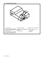
Diagnostic LED’s On Weld Interface Board PC12
LED
Status
Diagnosis
1
On
Indicates auxiliary output relay is not energized.
Off
Indicates auxiliary output relay is energized.
2
On
Indicates gas valve is not energized.
Off
Indicates gas valve is energized.
3
On
Ind24 volts dc is present for gas valve.
Off
Ind24 volts dc is not present for gas valve.
4
On
Ind15 volts dc is present on weld interface board PC12.
Off
Ind15 volts dc is not present on weld interface board PC12.
5
On
Indicates –15 volts dc is present on weld interface board PC12.
Off
Indicates –15 volts dc is not present on weld interface board PC12.
6
On
Ind15 volts dc power source supply is present on weld interface board PC12.
Off
Ind15 volts dc power source supply is not present on weld interface board PC12.
7
On
Indicates –15 volts dc power source supply is present on weld interface board PC12.
Off
Indicates –15 volts dc power source supply is not present on weld interface board PC12.
8
On
Ind5 volts dc is present on weld interface board PC12.
Off
Ind5 volts dc is not present on weld interface board PC12.
9
On
Input signal for no Jog retract.
Off
Input signal for Jog retract.
10
On
Input signal for no Jog advance.
Off
Input signal for Jog advance.
11
On
Indicates CV mode is selected.
Off
Indicates CC mode is selected.
12
On
Input signal for no welding power source contactor.
Off
Input signal for welding power source contactor.
13
On
Indicates an Emergency Stop condition is not present.
Off
Indicates an Emergency Stop condition is present.
Summary of Contents for Auto Invision II
Page 41: ...OM 196 188 Page 35 Notes ...
Page 43: ...OM 196 188 Page 37 203 505 A ...
Page 44: ...OM 196 188 Page 38 Figure 6 2 Circuit Diagram For Control Board PC1 Part 1 of 3 ...
Page 45: ...OM 196 188 Page 39 203 311 1 of 3 ...
Page 46: ...OM 196 188 Page 40 Figure 6 3 Circuit Diagram For Control Board PC1 Part 2 of 3 ...
Page 47: ...OM 196 188 Page 41 203 311 2 of 3 ...
Page 48: ...OM 196 188 Page 42 Figure 6 4 Circuit Diagram For Control Board PC1 Part 3 of 3 ...
Page 49: ...OM 196 188 Page 43 203 311 3 of 3 ...
Page 50: ...OM 196 188 Page 44 Figure 6 5 Circuit Diagram For Function Meter Board PC3 ...
Page 51: ...OM 196 188 Page 45 190 696 ...
Page 53: ...OM 196 188 Page 47 Notes ...
Page 54: ...OM 196 188 Page 48 Figure 6 8 Circuit Diagram For Interface Module ...
Page 55: ...OM 196 188 Page 49 193 709 A ...
Page 56: ...OM 196 188 Page 50 Figure 6 9 Circuit Diagram For Microprocessor Board PC11 ...
Page 57: ...OM 196 188 Page 51 191 838 ...
Page 58: ...OM 196 188 Page 52 Figure 6 10 Circuit Diagram For Motor Board PC13 ...
Page 59: ...OM 196 188 Page 53 212 354 A ...
Page 60: ...OM 196 188 Page 54 Figure 6 11 Circuit Diagram For Switch Board PC15 182 996 ...
Page 61: ...OM 196 188 Page 55 200 739 Figure 6 12 Circuit Diagram For Junction Board PC16 ...
Page 62: ...OM 196 188 Page 56 Figure 6 13 Circuit Diagram For Interface Board PC12 Part 1 of 2 ...
Page 63: ...OM 196 188 Page 57 191 843 A Part 1 of 2 ...
Page 64: ...OM 196 188 Page 58 Figure 6 14 Circuit Diagram For Interface Board PC12 Part 2 of 2 ...
Page 65: ...OM 196 188 Page 59 191 843 A Part 2 of 2 ...
Page 66: ...OM 196 188 Page 60 Figure 6 15 Circuit Diagram For Customer Interface Board PC14 Part 1 of 3 ...
Page 67: ...OM 196 188 Page 61 Pensar 86147s03 Part 1 of 3 ...
Page 68: ...OM 196 188 Page 62 Figure 6 16 Circuit Diagram For Customer Interface Board PC14 Part 2 of 3 ...
Page 69: ...OM 196 188 Page 63 Pensar 86147s03 Part 2 of 3 ...
Page 70: ...OM 196 188 Page 64 Figure 6 17 Circuit Diagram For Customer Interface Board PC14 Part 3 of 3 ...
Page 71: ...OM 196 188 Page 65 Pensar 86147s03 Part 3 of 3 ...
Page 72: ...OM 196 188 Page 66 Figure 6 18 Circuit Diagram For Touch Sensor Board PC18 174 578 A ...
Page 73: ...OM 196 188 Page 67 200 739 A Figure 6 19 Circuit Diagram For Setup Pendant ...
Page 75: ...OM 196 188 Page 69 191 531 Figure 6 21 Circuit Diagram For Power Distribution Board PC20 ...
Page 80: ...OM 196 188 Page 74 Notes ...
Page 81: ...Auto Invision II OM 196 188K July 2003 Programming Instructions for ...
Page 130: ......


