


OM-196 188 Page 10
> 60 s
V
S-179 190-A
V
V
1
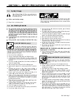
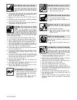
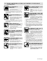
Warning! Watch Out! There
are possible hazards as
shown by the symbols.
2
Electric shock from wiring can
kill.
3
Disconnect input plug or
power before working on
machine.
4
Hazardous voltage remains
on input capacitors after
power is turned off. Do not
touch fully charged
capacitors.
5
Always wait 60 seconds after
power is turned off before
working on unit, OR
6
Check input capacitor voltage,
and be sure it is near 0 before
touching any parts.
4/96
1
2
3
4
5
6
S-179 304-A
1
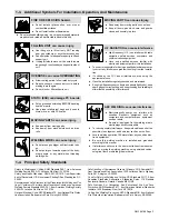
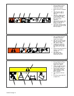
Warning! Watch Out! There
are possible hazards as
shown by the symbols.
2
When power is applied failed
parts can explode or cause
other parts to explode.
3
Flying pieces of parts can
cause injury. Always wear a
face shield when servicing
unit.
4
Always wear long sleeves and
button your collar when
servicing unit.
5
After taking proper
precautions as shown,
connect power to unit.
4/96
1
2
3
4
5
S-179 309-A
∠
= <60
°
∠
1
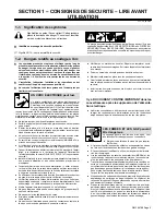
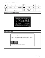
Warning! Watch Out! There
are possible hazards as
shown by the symbols.
2
Falling equipment can cause
injury and damage to unit.
3
Always lift and support unit
using both handles. Keep
angle of lifting device less
than 60 degrees.
4
Use a proper cart to move
unit.
5
Do not use one handle to lift
or support unit.
1/96
1
2
3
4
5
Summary of Contents for Auto Invision II
Page 41: ...OM 196 188 Page 35 Notes ...
Page 43: ...OM 196 188 Page 37 203 505 A ...
Page 44: ...OM 196 188 Page 38 Figure 6 2 Circuit Diagram For Control Board PC1 Part 1 of 3 ...
Page 45: ...OM 196 188 Page 39 203 311 1 of 3 ...
Page 46: ...OM 196 188 Page 40 Figure 6 3 Circuit Diagram For Control Board PC1 Part 2 of 3 ...
Page 47: ...OM 196 188 Page 41 203 311 2 of 3 ...
Page 48: ...OM 196 188 Page 42 Figure 6 4 Circuit Diagram For Control Board PC1 Part 3 of 3 ...
Page 49: ...OM 196 188 Page 43 203 311 3 of 3 ...
Page 50: ...OM 196 188 Page 44 Figure 6 5 Circuit Diagram For Function Meter Board PC3 ...
Page 51: ...OM 196 188 Page 45 190 696 ...
Page 53: ...OM 196 188 Page 47 Notes ...
Page 54: ...OM 196 188 Page 48 Figure 6 8 Circuit Diagram For Interface Module ...
Page 55: ...OM 196 188 Page 49 193 709 A ...
Page 56: ...OM 196 188 Page 50 Figure 6 9 Circuit Diagram For Microprocessor Board PC11 ...
Page 57: ...OM 196 188 Page 51 191 838 ...
Page 58: ...OM 196 188 Page 52 Figure 6 10 Circuit Diagram For Motor Board PC13 ...
Page 59: ...OM 196 188 Page 53 212 354 A ...
Page 60: ...OM 196 188 Page 54 Figure 6 11 Circuit Diagram For Switch Board PC15 182 996 ...
Page 61: ...OM 196 188 Page 55 200 739 Figure 6 12 Circuit Diagram For Junction Board PC16 ...
Page 62: ...OM 196 188 Page 56 Figure 6 13 Circuit Diagram For Interface Board PC12 Part 1 of 2 ...
Page 63: ...OM 196 188 Page 57 191 843 A Part 1 of 2 ...
Page 64: ...OM 196 188 Page 58 Figure 6 14 Circuit Diagram For Interface Board PC12 Part 2 of 2 ...
Page 65: ...OM 196 188 Page 59 191 843 A Part 2 of 2 ...
Page 66: ...OM 196 188 Page 60 Figure 6 15 Circuit Diagram For Customer Interface Board PC14 Part 1 of 3 ...
Page 67: ...OM 196 188 Page 61 Pensar 86147s03 Part 1 of 3 ...
Page 68: ...OM 196 188 Page 62 Figure 6 16 Circuit Diagram For Customer Interface Board PC14 Part 2 of 3 ...
Page 69: ...OM 196 188 Page 63 Pensar 86147s03 Part 2 of 3 ...
Page 70: ...OM 196 188 Page 64 Figure 6 17 Circuit Diagram For Customer Interface Board PC14 Part 3 of 3 ...
Page 71: ...OM 196 188 Page 65 Pensar 86147s03 Part 3 of 3 ...
Page 72: ...OM 196 188 Page 66 Figure 6 18 Circuit Diagram For Touch Sensor Board PC18 174 578 A ...
Page 73: ...OM 196 188 Page 67 200 739 A Figure 6 19 Circuit Diagram For Setup Pendant ...
Page 75: ...OM 196 188 Page 69 191 531 Figure 6 21 Circuit Diagram For Power Distribution Board PC20 ...
Page 80: ...OM 196 188 Page 74 Notes ...
Page 81: ...Auto Invision II OM 196 188K July 2003 Programming Instructions for ...
Page 130: ......


