


OM-196 188 Page 28
1
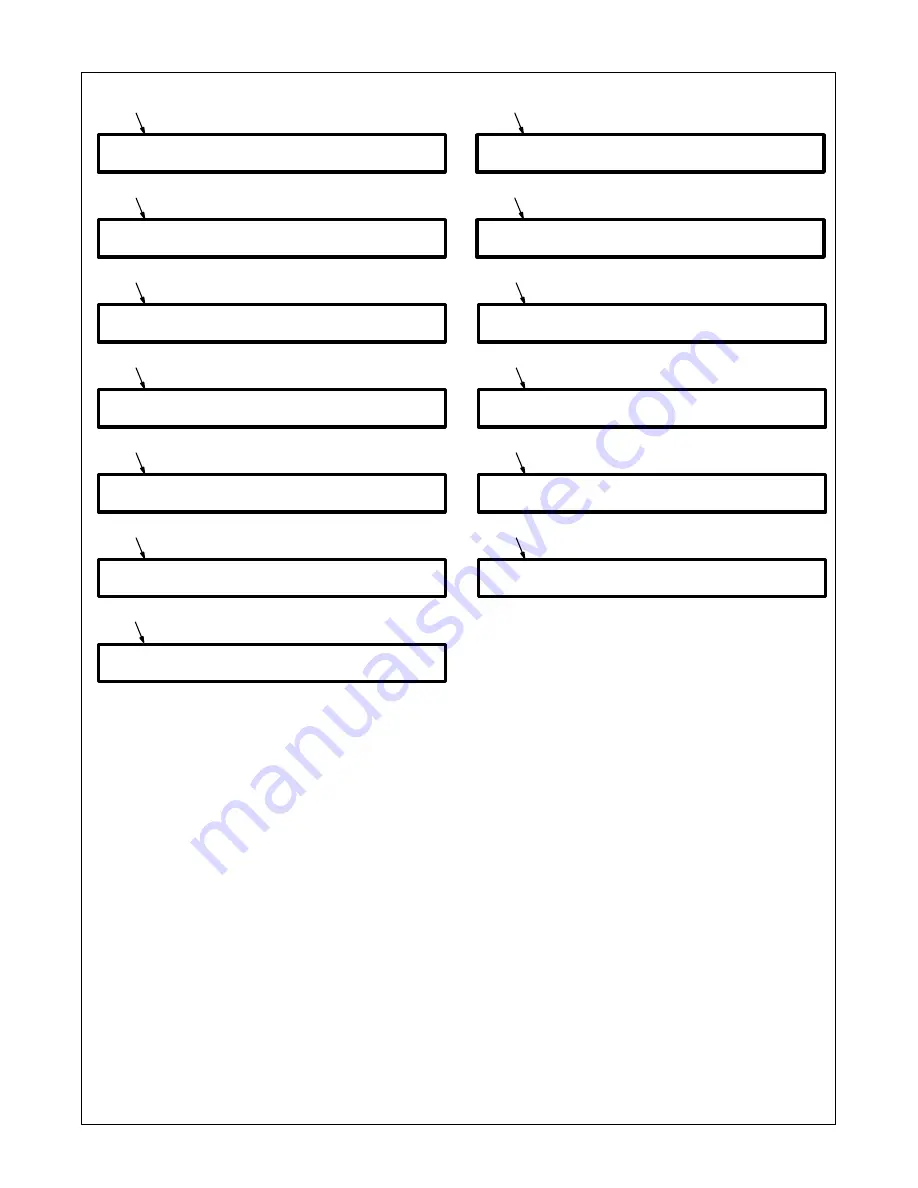
Memory CRC Error Display
Corrupted program data has been detected
or loaded. The “X” value indicates the pro-
gram number.
May be caused by incompatible information
on the data card or bad memory.
2
Memory Range Error Display
Improper welding power source range is
selected. The “X” value indicates the pro-
gram number.
May be caused by improper range settings
or improper data loaded into the interface
unit.
3
No Volt Sensed Error Display
The arc voltage sense circuit did not receive
feedback within the required time after an arc
was established.
May be caused by an inability to establish an
arc in the pulse schedule, or a lack of voltage
feedback.
4
No Tach Sensed Error Display
The motor tachometer feedback is not
reaching the control.
May be caused by obstructions in the wire
feed system or a faulty wire drive system.
5
Arc Stop Error Display
Trouble is occurring at arc end.
May be caused by obstructions in the wire
feed system or a faulty wire drive system or
torch is touching part at end of weld.
6
Arc Start Error Display
Trouble is occurring at arc start.
May be caused by obstructions in the wire
feed system or a faulty wire drive system.
7
Stop Weld Cycle Error Display
An error has been detected and the robot
hasn’t stopped the weld cycle, causing the
interface unit to stop the weld cycle and wait
for the robot to stop.
8
Error Card Read Display
The card reader is not working properly.
May be caused by a bad data card, a bad
data card reader, a faulty microprocessor
circuit board, or a wiring problem.
9
No Flow Detected
No coolant is detected after preflow in the
weld cycle. Check coolant system and flow
switch for proper operation.
10 Ground Current Detect Error Display
Weld current has been detected in the earth
ground connection.
May be caused by a conductor making
connection to the unit chassis.
11 Wire Stick Error Display
The welding wire has stuck to the workpiece
at the end of the weld.
May be caused by poor weld conditions.
12 Arc Fail Time Out Error Display
An arc was not established within the allotted
time.
May be caused by an inoperable wire drive,
absence of shield gas, or improperly operat-
ing welding power source.
13 No Input IPM Display
Analog IPM (inches per minute) from robot is
not being received.
May be caused by having no wire feed speed
programmed at the robot.
1
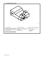
5-5.
Front Panel Error Displays
M e m
C R C
E r r o r
S t o p
W e l d
C y c l e
E r r
2
M e m
R a n g e
E r r
3
N o
V o l t
S e n s e d
E r r o r
4
N o
T a c h
S e n s e d
E r r o r
5
A r c
S t o p
E r r o r
6
A r c
S t a r t
E r r o r
7
8
E r r o r
C a r d
R e a d
9
N o
F l o w
D e t e c t e d
10
G r d
C u r r e n t
D e t e c t
11
W i r e
S t i c k
E r r o r
12
A r c
F a i l
T i m e O u t
E r r
13
N o
I n p u t
I P M
Summary of Contents for Auto Invision II
Page 41: ...OM 196 188 Page 35 Notes ...
Page 43: ...OM 196 188 Page 37 203 505 A ...
Page 44: ...OM 196 188 Page 38 Figure 6 2 Circuit Diagram For Control Board PC1 Part 1 of 3 ...
Page 45: ...OM 196 188 Page 39 203 311 1 of 3 ...
Page 46: ...OM 196 188 Page 40 Figure 6 3 Circuit Diagram For Control Board PC1 Part 2 of 3 ...
Page 47: ...OM 196 188 Page 41 203 311 2 of 3 ...
Page 48: ...OM 196 188 Page 42 Figure 6 4 Circuit Diagram For Control Board PC1 Part 3 of 3 ...
Page 49: ...OM 196 188 Page 43 203 311 3 of 3 ...
Page 50: ...OM 196 188 Page 44 Figure 6 5 Circuit Diagram For Function Meter Board PC3 ...
Page 51: ...OM 196 188 Page 45 190 696 ...
Page 53: ...OM 196 188 Page 47 Notes ...
Page 54: ...OM 196 188 Page 48 Figure 6 8 Circuit Diagram For Interface Module ...
Page 55: ...OM 196 188 Page 49 193 709 A ...
Page 56: ...OM 196 188 Page 50 Figure 6 9 Circuit Diagram For Microprocessor Board PC11 ...
Page 57: ...OM 196 188 Page 51 191 838 ...
Page 58: ...OM 196 188 Page 52 Figure 6 10 Circuit Diagram For Motor Board PC13 ...
Page 59: ...OM 196 188 Page 53 212 354 A ...
Page 60: ...OM 196 188 Page 54 Figure 6 11 Circuit Diagram For Switch Board PC15 182 996 ...
Page 61: ...OM 196 188 Page 55 200 739 Figure 6 12 Circuit Diagram For Junction Board PC16 ...
Page 62: ...OM 196 188 Page 56 Figure 6 13 Circuit Diagram For Interface Board PC12 Part 1 of 2 ...
Page 63: ...OM 196 188 Page 57 191 843 A Part 1 of 2 ...
Page 64: ...OM 196 188 Page 58 Figure 6 14 Circuit Diagram For Interface Board PC12 Part 2 of 2 ...
Page 65: ...OM 196 188 Page 59 191 843 A Part 2 of 2 ...
Page 66: ...OM 196 188 Page 60 Figure 6 15 Circuit Diagram For Customer Interface Board PC14 Part 1 of 3 ...
Page 67: ...OM 196 188 Page 61 Pensar 86147s03 Part 1 of 3 ...
Page 68: ...OM 196 188 Page 62 Figure 6 16 Circuit Diagram For Customer Interface Board PC14 Part 2 of 3 ...
Page 69: ...OM 196 188 Page 63 Pensar 86147s03 Part 2 of 3 ...
Page 70: ...OM 196 188 Page 64 Figure 6 17 Circuit Diagram For Customer Interface Board PC14 Part 3 of 3 ...
Page 71: ...OM 196 188 Page 65 Pensar 86147s03 Part 3 of 3 ...
Page 72: ...OM 196 188 Page 66 Figure 6 18 Circuit Diagram For Touch Sensor Board PC18 174 578 A ...
Page 73: ...OM 196 188 Page 67 200 739 A Figure 6 19 Circuit Diagram For Setup Pendant ...
Page 75: ...OM 196 188 Page 69 191 531 Figure 6 21 Circuit Diagram For Power Distribution Board PC20 ...
Page 80: ...OM 196 188 Page 74 Notes ...
Page 81: ...Auto Invision II OM 196 188K July 2003 Programming Instructions for ...
Page 130: ......


