


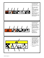


OM-196 188 Page 17
3-10. Peripheral Receptacle Functions
Function
Socket
Socket Information
Programmable
Output Relay Con-
A
Contact closure to B dependent upon state of
programmed output (see Section 14-5). The closure
between A and B can carry a maximum of 0.6
amps at 125 VAC; or a maximum of 0.6 amps at
110 VDC.
A
K
J
Output Relay Con-
tacts
B
Contact closure to A dependent upon state of
programmed output (see Section 14-5). See socket
A information for current carrying capacity of
closure.
A
K
B
M
J
C
C*
Circuit common.
M
C
L
H
D
E F
Purge
D
Contact closure to C completes 24 volts dc
solenoid circuit to purge shielding gas line.
E F
Coolant Flow
Switch Input
Signal
E
Contact closure to F indicates coolant flow switch is
closed and recirculating coolant system is
operational.
Signal
F*
Circuit common.
Jog +
H**
Contact closure to circuit common advances
welding wire at wire drive assembly.
802 748
Jog –
J**
Contact closure to circuit common retracts welding
wire at wire drive assembly.
K
Contact closure to L energizes Touch Sensor
circuitry.
Touch Sensor ON
And Output Signal
L*
Circuit common.
Touch Sensor ON
And Output Signal
M
{
Part touched is selectable for either 0 volts dc
(common) or +24 volts dc (see Section 3-12).
Part t24 volts dc output signal referenced
to circuit common is factory default setting.
*Circuit common is same electrical reference point.
**Speed of Jog + and Jog – is at setup value for Jog IPM parameter.
{
Socket M can be changed to 0 volts dc (common) for part touched output signal (see Section 3-12).
Note: A customer supplied matching amphenol plug [Miller Part No. 194 847 (Amphenol Part No. MS3106A20-33P and strain relief clamp
AN3057-12)] is required to use peripheral receptacle.
Summary of Contents for Auto Invision II
Page 41: ...OM 196 188 Page 35 Notes ...
Page 43: ...OM 196 188 Page 37 203 505 A ...
Page 44: ...OM 196 188 Page 38 Figure 6 2 Circuit Diagram For Control Board PC1 Part 1 of 3 ...
Page 45: ...OM 196 188 Page 39 203 311 1 of 3 ...
Page 46: ...OM 196 188 Page 40 Figure 6 3 Circuit Diagram For Control Board PC1 Part 2 of 3 ...
Page 47: ...OM 196 188 Page 41 203 311 2 of 3 ...
Page 48: ...OM 196 188 Page 42 Figure 6 4 Circuit Diagram For Control Board PC1 Part 3 of 3 ...
Page 49: ...OM 196 188 Page 43 203 311 3 of 3 ...
Page 50: ...OM 196 188 Page 44 Figure 6 5 Circuit Diagram For Function Meter Board PC3 ...
Page 51: ...OM 196 188 Page 45 190 696 ...
Page 53: ...OM 196 188 Page 47 Notes ...
Page 54: ...OM 196 188 Page 48 Figure 6 8 Circuit Diagram For Interface Module ...
Page 55: ...OM 196 188 Page 49 193 709 A ...
Page 56: ...OM 196 188 Page 50 Figure 6 9 Circuit Diagram For Microprocessor Board PC11 ...
Page 57: ...OM 196 188 Page 51 191 838 ...
Page 58: ...OM 196 188 Page 52 Figure 6 10 Circuit Diagram For Motor Board PC13 ...
Page 59: ...OM 196 188 Page 53 212 354 A ...
Page 60: ...OM 196 188 Page 54 Figure 6 11 Circuit Diagram For Switch Board PC15 182 996 ...
Page 61: ...OM 196 188 Page 55 200 739 Figure 6 12 Circuit Diagram For Junction Board PC16 ...
Page 62: ...OM 196 188 Page 56 Figure 6 13 Circuit Diagram For Interface Board PC12 Part 1 of 2 ...
Page 63: ...OM 196 188 Page 57 191 843 A Part 1 of 2 ...
Page 64: ...OM 196 188 Page 58 Figure 6 14 Circuit Diagram For Interface Board PC12 Part 2 of 2 ...
Page 65: ...OM 196 188 Page 59 191 843 A Part 2 of 2 ...
Page 66: ...OM 196 188 Page 60 Figure 6 15 Circuit Diagram For Customer Interface Board PC14 Part 1 of 3 ...
Page 67: ...OM 196 188 Page 61 Pensar 86147s03 Part 1 of 3 ...
Page 68: ...OM 196 188 Page 62 Figure 6 16 Circuit Diagram For Customer Interface Board PC14 Part 2 of 3 ...
Page 69: ...OM 196 188 Page 63 Pensar 86147s03 Part 2 of 3 ...
Page 70: ...OM 196 188 Page 64 Figure 6 17 Circuit Diagram For Customer Interface Board PC14 Part 3 of 3 ...
Page 71: ...OM 196 188 Page 65 Pensar 86147s03 Part 3 of 3 ...
Page 72: ...OM 196 188 Page 66 Figure 6 18 Circuit Diagram For Touch Sensor Board PC18 174 578 A ...
Page 73: ...OM 196 188 Page 67 200 739 A Figure 6 19 Circuit Diagram For Setup Pendant ...
Page 75: ...OM 196 188 Page 69 191 531 Figure 6 21 Circuit Diagram For Power Distribution Board PC20 ...
Page 80: ...OM 196 188 Page 74 Notes ...
Page 81: ...Auto Invision II OM 196 188K July 2003 Programming Instructions for ...
Page 130: ......


