


OM-196 188 Page 21
System Reset
By selecting system reset in the memory reset mode, the unit defaults to original factory settings for
all programs and all set up excluding System, Arc Time, and Model Type.
Voltage (Control Feedback)
Allows voltage to be monitored at the output terminals by two methods. This can be selected through
the internal connections of the unit, or through the unit’s external voltage sense lead.
When using the V. Sense setting, arc voltage feedback is through the voltage sense leads connected
to the feeder. Use this setting when there is more than 50 ft (15 m) of weld cable used.
Arc Start/Volt Sense Shutdown
When this feature is on, the system immediately shuts down if no arc voltage is sensed. An error
message is displayed. When this feature is off, wire feeds even when there is no arc voltage sensed.
Wire Feed Mode
Allows the selection of inches per minute or meters per minute for wire feed speed. This mode is also
used to select motor type; standard speed, low speed, or high speed.
4-2.
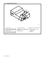
Lower Front Panel Controls
1
Power Switch
.
The fan motor is thermostatically
controlled and only runs when cooling is
needed.
2
Voltmeter (see Section 4-3)
3
Ammeter (see Section 4-3)
2
3
Ref. 186 067
1
CE
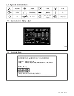
4-3.
Meter Functions
The meters display the actual weld output values for approximately three seconds after the arc
is broken.
Note
Mode
Meter Reading At Idle
Meter Reading While Welding
MIG
Preset Volts
Blank
V
A
24.5
Actual Volts
Actual Amps
V
A
24.5
250
Pulsed
MIG
Pulse Display
Pulse Display
V
A
PPP
PPP
Actual Volts
Actual Amps
V
A
24.5
250
Summary of Contents for Auto Invision II
Page 41: ...OM 196 188 Page 35 Notes ...
Page 43: ...OM 196 188 Page 37 203 505 A ...
Page 44: ...OM 196 188 Page 38 Figure 6 2 Circuit Diagram For Control Board PC1 Part 1 of 3 ...
Page 45: ...OM 196 188 Page 39 203 311 1 of 3 ...
Page 46: ...OM 196 188 Page 40 Figure 6 3 Circuit Diagram For Control Board PC1 Part 2 of 3 ...
Page 47: ...OM 196 188 Page 41 203 311 2 of 3 ...
Page 48: ...OM 196 188 Page 42 Figure 6 4 Circuit Diagram For Control Board PC1 Part 3 of 3 ...
Page 49: ...OM 196 188 Page 43 203 311 3 of 3 ...
Page 50: ...OM 196 188 Page 44 Figure 6 5 Circuit Diagram For Function Meter Board PC3 ...
Page 51: ...OM 196 188 Page 45 190 696 ...
Page 53: ...OM 196 188 Page 47 Notes ...
Page 54: ...OM 196 188 Page 48 Figure 6 8 Circuit Diagram For Interface Module ...
Page 55: ...OM 196 188 Page 49 193 709 A ...
Page 56: ...OM 196 188 Page 50 Figure 6 9 Circuit Diagram For Microprocessor Board PC11 ...
Page 57: ...OM 196 188 Page 51 191 838 ...
Page 58: ...OM 196 188 Page 52 Figure 6 10 Circuit Diagram For Motor Board PC13 ...
Page 59: ...OM 196 188 Page 53 212 354 A ...
Page 60: ...OM 196 188 Page 54 Figure 6 11 Circuit Diagram For Switch Board PC15 182 996 ...
Page 61: ...OM 196 188 Page 55 200 739 Figure 6 12 Circuit Diagram For Junction Board PC16 ...
Page 62: ...OM 196 188 Page 56 Figure 6 13 Circuit Diagram For Interface Board PC12 Part 1 of 2 ...
Page 63: ...OM 196 188 Page 57 191 843 A Part 1 of 2 ...
Page 64: ...OM 196 188 Page 58 Figure 6 14 Circuit Diagram For Interface Board PC12 Part 2 of 2 ...
Page 65: ...OM 196 188 Page 59 191 843 A Part 2 of 2 ...
Page 66: ...OM 196 188 Page 60 Figure 6 15 Circuit Diagram For Customer Interface Board PC14 Part 1 of 3 ...
Page 67: ...OM 196 188 Page 61 Pensar 86147s03 Part 1 of 3 ...
Page 68: ...OM 196 188 Page 62 Figure 6 16 Circuit Diagram For Customer Interface Board PC14 Part 2 of 3 ...
Page 69: ...OM 196 188 Page 63 Pensar 86147s03 Part 2 of 3 ...
Page 70: ...OM 196 188 Page 64 Figure 6 17 Circuit Diagram For Customer Interface Board PC14 Part 3 of 3 ...
Page 71: ...OM 196 188 Page 65 Pensar 86147s03 Part 3 of 3 ...
Page 72: ...OM 196 188 Page 66 Figure 6 18 Circuit Diagram For Touch Sensor Board PC18 174 578 A ...
Page 73: ...OM 196 188 Page 67 200 739 A Figure 6 19 Circuit Diagram For Setup Pendant ...
Page 75: ...OM 196 188 Page 69 191 531 Figure 6 21 Circuit Diagram For Power Distribution Board PC20 ...
Page 80: ...OM 196 188 Page 74 Notes ...
Page 81: ...Auto Invision II OM 196 188K July 2003 Programming Instructions for ...
Page 130: ......


