


OM-196 188 Page 27
5-4.
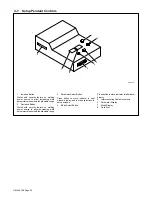
Voltmeter/Ammeter Help Displays
.
All directions are in reference to
the front of the unit. All circuitry
referred to is located inside the
unit.
1
Help 1 Display
Indicates a malfunction in the
primary power circuit. If this display
is shown, contact a Factory
Authorized Service Agent.
2
Help 2 Display
Indicates a malfunction in the
thermal protection circuitry located
on the left side of the unit. If this
display is shown, contact a Factory
Authorized Service Agent.
3
Help 3 Display
Indicates the left side of the unit has
overheated. The unit has shut down
to allow the fan to cool it (see Sec-
tion 4-5). Operation will continue
when the unit has cooled.
4
Help 4 Display
Indicates a malfunction in the
thermal protection circuitry located
on the right side of the unit. If this
display is shown, contact a Factory
Authorized Service Agent.
5
Help 5 Display
Indicates the right side of the unit
has overheated. The unit has shut
down to allow the fan to cool it (see
Section 4-5). Operation will
continue when the unit has cooled.
6
Help 6 Display
Indicates that the input voltage is
too low and the unit has
automatically shut down. Operation
will continue when the voltage is
within
±
15% of the operating range.
If this display is shown, have an
electrician check the input voltage.
7
Help 7 Display
Indicates that the input voltage is
too high and the unit has
automatically shut down. Operation
will continue when the voltage is
within
±
15% of the operating range.
If this display is shown, have an
electrician check the input voltage.
8
Help 8 Display
Indicates a malfunction in the sec-
ondary power circuit of the unit. If
this display is shown, contact a
Factory Authorized Service Agent.
In addition, when the optional
ground current sensor is installed,
this display indicates weld current
in the ground conductor. When this
occurs, have an electrician check
the primary and secondary
connections.
1
A
V
2
A
V
3
A
V
HE.L
P–1
HE.L
P–2
HE.L
P–3
4
A
V
HE.L
P–4
5
A
V
HE.L
P–5
6
A
V
HE.L
P–6
7
A
V
HE.L
P–7
8
A
V
HE.L
P–8
Summary of Contents for Auto Invision II
Page 41: ...OM 196 188 Page 35 Notes ...
Page 43: ...OM 196 188 Page 37 203 505 A ...
Page 44: ...OM 196 188 Page 38 Figure 6 2 Circuit Diagram For Control Board PC1 Part 1 of 3 ...
Page 45: ...OM 196 188 Page 39 203 311 1 of 3 ...
Page 46: ...OM 196 188 Page 40 Figure 6 3 Circuit Diagram For Control Board PC1 Part 2 of 3 ...
Page 47: ...OM 196 188 Page 41 203 311 2 of 3 ...
Page 48: ...OM 196 188 Page 42 Figure 6 4 Circuit Diagram For Control Board PC1 Part 3 of 3 ...
Page 49: ...OM 196 188 Page 43 203 311 3 of 3 ...
Page 50: ...OM 196 188 Page 44 Figure 6 5 Circuit Diagram For Function Meter Board PC3 ...
Page 51: ...OM 196 188 Page 45 190 696 ...
Page 53: ...OM 196 188 Page 47 Notes ...
Page 54: ...OM 196 188 Page 48 Figure 6 8 Circuit Diagram For Interface Module ...
Page 55: ...OM 196 188 Page 49 193 709 A ...
Page 56: ...OM 196 188 Page 50 Figure 6 9 Circuit Diagram For Microprocessor Board PC11 ...
Page 57: ...OM 196 188 Page 51 191 838 ...
Page 58: ...OM 196 188 Page 52 Figure 6 10 Circuit Diagram For Motor Board PC13 ...
Page 59: ...OM 196 188 Page 53 212 354 A ...
Page 60: ...OM 196 188 Page 54 Figure 6 11 Circuit Diagram For Switch Board PC15 182 996 ...
Page 61: ...OM 196 188 Page 55 200 739 Figure 6 12 Circuit Diagram For Junction Board PC16 ...
Page 62: ...OM 196 188 Page 56 Figure 6 13 Circuit Diagram For Interface Board PC12 Part 1 of 2 ...
Page 63: ...OM 196 188 Page 57 191 843 A Part 1 of 2 ...
Page 64: ...OM 196 188 Page 58 Figure 6 14 Circuit Diagram For Interface Board PC12 Part 2 of 2 ...
Page 65: ...OM 196 188 Page 59 191 843 A Part 2 of 2 ...
Page 66: ...OM 196 188 Page 60 Figure 6 15 Circuit Diagram For Customer Interface Board PC14 Part 1 of 3 ...
Page 67: ...OM 196 188 Page 61 Pensar 86147s03 Part 1 of 3 ...
Page 68: ...OM 196 188 Page 62 Figure 6 16 Circuit Diagram For Customer Interface Board PC14 Part 2 of 3 ...
Page 69: ...OM 196 188 Page 63 Pensar 86147s03 Part 2 of 3 ...
Page 70: ...OM 196 188 Page 64 Figure 6 17 Circuit Diagram For Customer Interface Board PC14 Part 3 of 3 ...
Page 71: ...OM 196 188 Page 65 Pensar 86147s03 Part 3 of 3 ...
Page 72: ...OM 196 188 Page 66 Figure 6 18 Circuit Diagram For Touch Sensor Board PC18 174 578 A ...
Page 73: ...OM 196 188 Page 67 200 739 A Figure 6 19 Circuit Diagram For Setup Pendant ...
Page 75: ...OM 196 188 Page 69 191 531 Figure 6 21 Circuit Diagram For Power Distribution Board PC20 ...
Page 80: ...OM 196 188 Page 74 Notes ...
Page 81: ...Auto Invision II OM 196 188K July 2003 Programming Instructions for ...
Page 130: ......


