background image

14

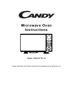
C. DETERMINING WALL PLATE LOCATION UNDER YOUR CABIN ET

Plate position-beneath flat bottom cabinet.

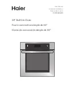
Plate position-beneath recessed bottom cabinet with front overhang

²

At least 30

C

3/8" TO EDGE

%#76+10Ä+(

':*#756

#&#2614+

5215+6+10

'&1765+&

'

4'%1//'

0&'&&+/'

05+10)4

'#5'Ä.#&'

0#+49+..

&

+5%*#4)

'+061*175

'5647%6

74'

/+0+/7/9

+&6*4'37+4'&

4'#49#..6'/2.#6'

NOTE: IT IS

 VERY IMP

ORTANT TO

READ AND

 FOLLOW

 THE DIRE

CTIONS

IN THE INS

TALLATIO

N INSTRU

CTIONS

BEFORE P

ROCEEDI

NG WITH T

HIS

REAR WALL 

TEMPLATE

.

This Rear W

all Template

 serves to po

sition the bo

ttom 

mounting pla

te and to loc

ate the horiz

ontal exhaust


outlet. 

1. Use a level

 to check tha

t the templa

te is position

ed 

    accurately. 

2. Locate an

d mark at lea

st one stud o

n the left or 

    right side of 

the centerlin

e.

016'

It is importa

nt to use at l

east one wo

od 

screw moun

ted firmly 

in a stud to s

upport the we

ight 

of the microw

ave. Mark tw

o additional, e

venly space

locations for the

 supplied tog

gle bolts. 

3. Drill holes

 in the marke

d locations. W

here there is 

    a stud, dr

ill a 3/16" h

ole for woo

d screws. F

or holes 

    that do n

ot line up wi

th a stud, dri

ll 5/8" holes fo

    toggle bolt

s. 

016'

DO NOT IN

STALL THE

 MOUNTING 

PLATE

AT THIS TIME. 

4. Remove

 the template

 from the re

ar wall. 

5. Review th

e Installation

 Instruction

 book for you

    installatio

n situation. 

Locate and

 mark hole

s to align w

ith holes in 

the 

mounting 

plate. 

IMPORTAN

T: 

LOCATE A

T LEAST

 ONE STUD

 ON EITH

ER SIDE 

OF 

THE CENT

ERLINE. 

MARK THE

 LOCATIO

N FOR 2 A

DDITIONAL

, EVENL

SPACED

 TOGGLE B

OLTS IN T

HE MOU

NTING PL

ATE

AREA.

Locate and

 mark hole

s to align

 with holes

 in the 

mounting pl

ate. 

IMPORTANT

LOCAT

E AT LEA

ST ONE ST

UD ON EIT

HER SIDE

 OF 

THE CENT

ERLINE. 

MARK THE

 LOCATIO

N FOR 2 A

DDITION

AL, EVENLY 

SPACED 

TOGGLE

 BOLTS IN

 THE MOUN

TING PLATE

AREA.

Trim the re

ar wall tem

plate along

 the dotted l

ine. 

Trim the re

ar wall temp

late along t

he dotted li

ne. 

%

#

$

%

&

(%76176(1

4*14+<106#.

17

65+&'':

*#756

%76*1.'

6*417)*4'#

49#..(

14':*#75

6#&#2614

12"

4"

Darle vuelta

 a la hoja pa

ra consultar

 la 

versión en Esp

añol.

16-1/2

1/4"

Minimum

 clearance

Draw a vertical line on the wall at the 
 
Tape the Rear Wall Template onto the wall
matching the centerline and touching the
bottom of the cabinet.

to Cooktop

C

3/8" TO EDGE

%#76+10Ä

+(':*#75

6#&#2614

+5215+6+10

'&1765+&

'

4'%1//

'0&'&&+/

'05+10

)4'#5'

Ä.#&'0#+4

9+..

&+

5%*#4)'

+061*1

75'5647

%674'

/+0+/7

/9+&6*4'

37+4'&

4'#49#..

6'/2

.#6'

NOTE: IT I

S VERY IM

PORTANT T

O

READ AN

D FOLLO

W THE DIR

ECTIONS

IN THE IN

STALLAT

ION INS

TRUCTIO

NS

BEFORE P

ROCEEDIN

G WITH

 THIS

REAR WALL

 TEMPLA

TE.

This Rea

r Wall Tem

plate serves 

to position th

e bottom 

mounting p

late and to lo

cate the ho

rizontal exh

aust 

outlet. 

1. Use a lev

el to check

 that the temp

late is positio

ned 

    accura

tely. 

2. Locate an

d mark at le

ast one stud on

 the left or 

    right side

 of the cen

terline.

016'

It is importa

nt to use at

 least one w

ood 

screw mou

nted firmly 

in a stud to su

pport the weigh

of the micro

wave. Mark

 two additiona

l, evenly sp

aced 

locations fo

r the supplie

d toggle bo

lts. 

3. Drill hole

s in the mar

ked location

s. Where

 there is 

    a stud, dr

ill a 3/16" ho

le for wood 

screws. For 

holes 

    that do n

ot line up w

ith a stud, d

rill 5/8" hole

s for 

    toggle bo

lts. 

016'

DO NOT IN

STALL THE

 MOUNTIN

G PLATE

AT THIS TIME

4. Remove

 the templat

e from the 

rear wall. 

5. Review 

the Installatio

n Instruction

 book for yo

ur 

    installatio

n situation. 

Locate and

 mark hole

s to align w

ith holes in

 the 

mounting p

late. 

IMPORTA

NT: 

LOCATE AT

 LEAST ON

E STUD ON

 EITHER S

IDE OF 

THE CEN

TERLIN

E. 

MARK TH

E LOCATION

 FOR 2 AD

DITIONAL

, EVENLY


SPACED 

TOGGLE

 BOLTS IN T

HE MOU

NTING PL

ATE

AREA.

Locate and

 mark hole

s to align w

ith holes in

 the 

mounting

 plate. 

IMPORTA

NT: 

LOCATE

 AT LEAS

T ONE STU

D ON E

ITHER SID

E OF 

THE CEN

TERLINE. 

MARK TH

E LOCATION

 FOR 2 AD

DITIONAL

, EVENLY 

SPACED T

OGGLE B

OLTS IN T

HE MOUN

TING PL

ATE

AREA.

Trim the r

ear wall te

mplate alo

ng the do

tted line. 

Trim the re

ar wall tem

plate alon

g the dotte

d line. 

%

#

$

%

&

(%7617

6(14

*14+<106#

.

1765+

&'':*#756

%76*1.'

6*417)*

4'#49#.

.(14':*#

756#&#2

614

12"

4"

Darle vuelt

a a la hoja

 para cons

ultar la 

versión en

 Español.

3/8" TO EDGE

%#76+10

Ä+(':*#

756#&#

2614+5215

+6+10'&1

765+&'

4'%1//

'0&'&&+

/'05+10

)4'#5'

Ä.#&'0#+

49+..

&+5

%*#4)'+06

1*175'5

647%674'

/+0+/7

/9+&6*4

'37+4'&

4'#49#..6'/2.#6'

NOTE: IT 

IS VER

Y IMPOR

TANT T

O

READ AN

D FOLLO

W TH

E DIREC

TIONS

IN THE IN

STALLAT

ION INST

RUCTION

S

BEFORE 

PROCEED

ING WITH

 THIS

REAR W

ALL TEMPL

ATE.

This Rear W

all Template s

erves to pos

ition the botto

mounting p

late and to l

ocate the h

orizontal e

xhaust 

outlet. 

1. Use a lev

el to che

ck that the te

mplate is

 positioned 

    accurately

2. Locate a

nd mark at le

ast one stud

 on the left 

or 

    right side

 of the cente

rline.

016'

It is importa

nt to use a

t least one w

ood 

screw mo

unted firmly

 in a stud to

 support the

 weight 

of the mic

rowave. Ma

rk two addit

ional, evenl

y spaced 

locations fo

r the supp

lied toggle b

olts. 

3. Drill hole

s in the ma

rked locatio

ns. Where 

there is 

    a stud, d

rill a 3/16" h

ole for wo

od screws. For

 holes 

    that do n

ot line up w

ith a stud, d

rill 5/8" hole

s for 

    toggle bo

lts. 

016'

DO NOT INSTA

LL THE MO

UNTING PL

ATE

AT TH

IS TIME. 

4. Remove th

e template fr

om the rea

r wall. 

5. Review the

 Installatio

n Instruction

 book for you

    installa

tion situatio

n. 

Locate an

d mark hol

es to ali

gn with hol

es in the 

mounting pl

ate. 

IMPORTAN

T: 

LOCATE AT

 LEAST 

ONE ST

UD ON EI

THER SID

E OF 

THE CEN

TERLIN

E. 

MARK TH

E LOC

ATION FOR

 2 ADDITION

AL, EVEN

LY 

SPAC

ED TOG

GLE BO

LTS IN TH

E MOUN

TING PLATE

AREA.

Locate 

and mark 

holes to al

ign with hol

es in the 

mounting pl

ate. 

IMPOR

TANT: 

LOCATE AT

 LEAS

T ONE ST

UD ON EI

THER SID

E OF 

THE CEN

TERLIN

E. 

MARK THE 

LOCATIO

N FOR 2 AD

DITIONAL

, EVEN

LY 

SPACED T

OGGLE 

BOLTS IN

 THE MO

UNTING

PLA

AREA.

Trim the re

ar wall t

emplate al

ong the d

otted line. 

Trim the rear

 wall tem

plate along

 the dotted 

line. 

%

$

&

(%76176

(14*14+<1

06#.

1765+

&'':*#756

%76*1.'

6*417)

*4'#49#

..(14'

:*#756

#&#2614

12"

4"

Darle vuel

ta a la hoja

 para cons

ultar la 

versión en 

Español.

30

1/4"

Minimum

 clearance

Draw a line on the

back wall equal to the 
depth of the front

overhang.

1/4"

Minimum

 clearance

Summary of Contents for TM05K6BW-P

Page 1: ...TRUCTIONS CAREFULLY Read these instructions carefully before using your microwave oven and keep it carefully If you follow the instructions your oven will provide you with many years of good service M...

Page 2: ...face and the door or allows soil or cleaner residue to accumulate on sealing surfaces c Do not operate the oven if it is damaged It is particularly important that the oven door close properly and tha...

Page 3: ...tment 10 Do not cover or block any openings on the appliance 11 Do not store this appliance outdoors Do not use this product near water for example near a kitchen sink in a wet basement near a swimmin...

Page 4: ...versized food or oversized metal utensils should not be inserted in a microwave toaster oven as they may create a fire or risk of electric shock 19 Do not clean with metal scouring pads Pieces can bur...

Page 5: ...ord shall be equal to or greater than the electrical rating of the appliance DANGER Electric Shock Hazard Touching some of the internal components can cause serious personal injury or death Do not dis...

Page 6: ...ceiver 4 Move the microwave oven away from the receiver 5 Plug the microwave oven into a different outlet so that microwave oven and receiver are on different branch circuits RADIO INTERFERENCE 6 FCC...

Page 7: ...ave oven There may be certain non metallic utensils that are not safe to use for microwaving If in doubt you can test the utensil in question following the procedure below Utensil Test 1 Fill a microw...

Page 8: ...to 50 pounds 22 7 kg or a total weight of 113 135 pounds 51 3 61 2 kg CAUTION For personal safety this product cannot be installed in cabinet arrangements such as an island or a peninsula It must be...

Page 9: ...eptacle is encountered it is very important to have it replaced with a properly grounded three prong wall receptacle installed by a qualified electrician DO NOT UNDER ANY CIRCUMSTANCES CUT DEFORM OR R...

Page 10: ...TALLATION INSTRUCTIONS QUANTITY Top Cabinet Template RearWall Template Installation Instructions Separately Packed Grease Filters 1 1 1 Exhaust adaptor 1 Glass Tray 1 Turntabl Ring 1 Convection wire r...

Page 11: ...r cord clearance As a guide to installation see page 25 for Mounting Template Information If the cabinet depth including the cabinet doors is more than 13 then the unit must be spaced out from wall us...

Page 12: ...oven please note Do Not Remove plastic plug protective cover until just before hanging the unit Keep the unit at least 8 inches away from the counter top edge to preven t dropping becau se of the hea...

Page 13: ...A Stud find er amagneticdevice which locatesnails B Use ahammerto taplightly across the mounting surface to find asolid sound This willindicateastudlocation 2 After locating the stud s find the center...

Page 14: ...Mark two additional evenly spaced locations for the supplied toggle bolts 3 Drill holes in the marked locations Where there is a stud drill a 3 16 hole for wood screws For holes that do not line up wi...

Page 15: ...OCATE AT LEAST ONE STUD ON EITHER SIDE OF THE CENTERLI NE MARK THE LOCATION FOR 2 ADDITION AL EVENLY SPACED TOGGLE BOLTS IN THE MOUNTING PLATE AREA Locate and mark holes to align with holes in the mou...

Page 16: ...allation situation Locate and mark holes to align with holes in the mounting plate IMPORTANT LOCATE AT LEAST ONE STUD ON EITHER SIDE OF THE CENTERLINE MARK THE LOCATION FOR 2 ADDITIONAL EVENLY SPACED...

Page 17: ...t NOTE This microwave is shipped assembled for Recirculating Select thetype of ventilation required for your installation and proceed to that section A RECIRCULATING NON VENTED DUCTLESS B OUTSIDE BACK...

Page 18: ...ed accurately 2 Locate and mark at least one stud on the left or right side of the centerline It is important to use at least one wood screw mounted firmly in a stud to support the weight of the micro...

Page 19: ...150 Ibs to allow proper top vent air exhaust intake 1 Remove the toggle wings from the bolts 2 Insert the bolts into the mounting plate through the holes designated to go into drywall To use toggle bo...

Page 20: ...rneath the top cabinet NOTE Adjust top template accordingly if the microwave is being spaced out from the wall due to cabinet depth including cabinet doors of more than 13 Drill the holes following th...

Page 21: ...not used case damage may occur from overtightening screws NOTE When mounting the microwave oven thread power cord through hole in bottom of top cabinet Keep it tight throughout Steps 1 3 Do not pinch...

Page 22: ...2 self aligning screws through outer top cabinet holes Turn two full turns on each screw 7 Tighten the outer two screws to the top of the microwave oven While tightening screws hold the microwave oven...

Page 23: ...access door follow these steps to replace or install a charcoal filter A5 1 Unplug microwave oven or disconnect power A5 2 Open the microwave door and remove the two vent mounting screws located on t...

Page 24: ...orrect position A5 6 Reinstall the vent by sliding the bottom of the vent into place Push the vent top into position and slide right into place Replace the two vent mounting screws located on top of t...

Page 25: ...not exceed 140 equivalentfeet 42 7 m Elbows transitions wall and roof caps etc present additional resistance to airflow and are equivalent to a section of straight duct which is longer than their act...

Page 26: ...15 2 cm Round 5 Ft 1 5 m x 1 5 Ft 1 5 m Rectangular to Round Transition Adaptor Equivalent lengths of duct pieces are based on actual tests and IMPORTANT If a rectangular to round transition adaptor i...

Page 27: ...ood screw mounted firmly in a stud to support the weight of the microwave Mark two additional evenly spaced locations for the supplied toggle bolts 3 Drill holes in the marked locations Where there is...

Page 28: ...ne wood screw must be used to attach the plate to a wall stud 1 Remove the toggle wings from the bolts 2 Insert the bolts into the mounting plate through the holes designated to go into drywall 3 Plac...

Page 29: ...large enough for the power cord to fit through Read the instructions on the TOP CABINET TEMPLATE Tape it underneath the top cabinet Drill the holes following the instructions on the TOP CABINET TEMPL...

Page 30: ...on other side of the blower unit 6 Roll the blower unit 90 so that fan blade openings are facing out the back of the microwave Back of Microwave Back of Microwave After Rotation Before Rotation After...

Page 31: ...rowave with the original screw Back of mircrowave Knockout Plates Snip all 4 webs on each knockout panel and remove the metal knockouts for rear airflow Please take care to remove any sharp edges crea...

Page 32: ...not used case damage may occur from overtightening screws NOTE When mounting the microwave oven thread power cord through hole in bottom of top cabinet Keep it tight throughout Steps 1 3 Do not pinch...

Page 33: ...ews to the top of the microwave oven While tightening screws hold the microwave oven in place against the wall and the top cabinet 8 Install grease filters See the Use and Care packed with the microwa...

Page 34: ...aust outlet 1 Use a level to check that the template is positioned accurately 2 Locate and mark at least one stud on the left or right side of the centerline It is important to use at least one wood s...

Page 35: ...r safety goggles when drilling holes in the cabinet bottom Place the mounting plate against the wall and insert the toggle wings into the holes in the wall to mount the plate NOTE Before tightening to...

Page 36: ...oll the blower unit 90 so that fan blade openings are facing out the top of the microwave 4 Place the blower unit back into the opening CAUTION Do not pull or stretch the blower unit wiring Make sure...

Page 37: ...w you to adjust the blower unit 3 Roll the blower unit 90 so that fan blade openings are facing out the top of the microwave Remove the screw that holds the blower plate to the microwave Remove and sa...

Page 38: ...7 Attach the exhaust adaptor to the top of the blower plate by sliding it into the guides of the blower plate Push in securely until it is in the locking tabs Take care to assure that the damper hing...

Page 39: ...FOR EASIER INSTALLATION AND PERSONAL SAFETY WE RECOMMEND THATTWO PEOPLE INSTALL THIS MICROWAVE OVEN IMPORTANT Do not grip or use the handle or heat shield during installation Do not remove the cardboa...

Page 40: ...cabinet hole Temporarily secure the oven by turning the screw at least two full turns after the threads have engaged It will be completely tightened later Be sure to keep power cord tight Be careful n...

Page 41: ...ood producing golden brown exteriors and rich moist interiors This circulation of heated air is called convection Because the heated air is kept constantly moving not permitting a layer of cooler air...

Page 42: ...amic baking containers are recommended Be sure not to use items with metal trim as it may cause arcing sparking with oven wall or oven shelf This can damage the cookware the shelf or the oven Heat Res...

Page 43: ...Light Hi Low Off Parameter Setting USER PREF Vent Hi med low off Wifi Function Increase Decrease 43 CONTROL PANEL...

Page 44: ...rate unless the door is securely closed 8 Ventilation openings 9 Removable turntable The turntable will rotate clockwise or counterclockwise Only remove for cleaning 10 Removable turntable support Fir...

Page 45: ...r 30 seconds Press and hold for 8 seconds till a beep sounds flashes for few seconds if the link has been removed successfully the screen will display 8888 and then return to standby mode 3 seconds if...

Page 46: ...rocess and pause state you can press COOK TIME TIMER to check Timer If microwave or menu cooking ends first the screen displays END If the Timer ends first buzzer will sound At the same time the buzze...

Page 47: ...ght of food 4 Press START Enter 30sec to start defrosting 5 Popcorn 1 Press POPCORN once twice or three times to select the weight of popcorn you want 3 3 3 0 and 1 75 Oz will display in order You als...

Page 48: ...art cooking 1 Press SENSOR COOK repeatedly to select the food you want 2 Press START Enter 30sec to confirm 3 Press a number key to set amount You also can press to adjust it 4 Press START Enter 30sec...

Page 49: ...t it 4 Press START Enter 30sec to start cooking Note If the amount weight of the menu cannot be adjust you can ignore the step 2 and 3 Note If the amount weight of the menu cannot be adjust you can ig...

Page 50: ...u need to open then close the oven door before 5 minutes Otherwise when you press number key to start speedy cooking LED will display FOOD Open then close the door and press START Enter 30sec to start...

Page 51: ...the light will start working 15 Vent 16 Light Key x 1 HIGH LOW OFF x 2 x 3 Level 14 Multi Stage Cooking 1 Press COOK TIME TIMER once and then ENTER COOK TIME will display 2 Press number keys to enter...

Page 52: ...Press START Enter 30sec three times TT OFF will display if you start cooking except auto menu and defrost in 5 minutes the turntable will work as your setting otherwise the turntable will return to on...

Page 53: ...times Lb KG will display in order 2 Press START Enter 30sec to confirm the unit 20 Unit Of Weight Setting 1 Press USER PREF five times DEMO OFF or DEMO ON will display 2 Press START Enter 30sec to con...

Page 54: ...Food is not defrosted completely c Cooking time power level is not suit ble d Food is not turned or stirred a Use microwave safe cookware only b Completely defrost food c Use correct cooking time pow...

Page 55: ......

Page 56: ......

Reviews: