background image


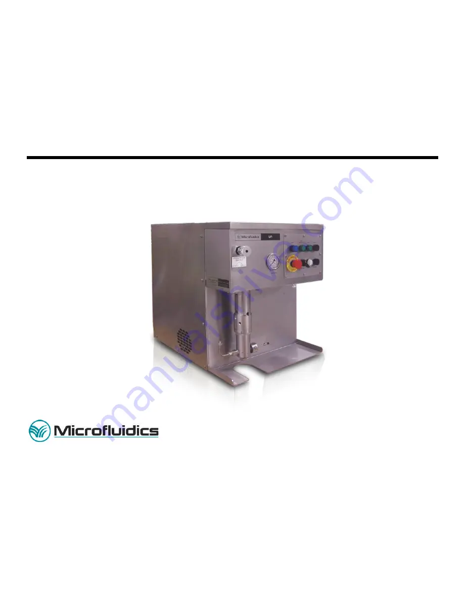
MODEL LV1 SERIES  

MICROFLUIDIZER

® 

PROCESSOR 

User Manual 


30 Ossipee Rd 
P.O. Box 9101 
Newton, MA 02464-9101 
 
Phone 617-969-5452 
Fax 617-965-1213 
[email protected] 
www.microfluidicscorp.com 


Part No. 85.0098 


Summary of Contents for MICROFLUIDIZER LV1 Series

Page 1: ...MODEL LV1 SERIES MICROFLUIDIZER PROCESSOR User Manual 30 Ossipee Rd P O Box 9101 Newton MA 02464 9101 Phone 617 969 5452 Fax 617 965 1213 mixinginfo mfics com www microfluidicscorp com Part No 85 0098 ...

Page 2: ...eserved This manual may not be copied photocopied reproduced translated converted to an electronic or machine readable form in whole or in part or distributed to customers or other third parties without prior written approval of Microfluidics International Corporation ...

Page 3: ...w 6 ml stroke at full 2 5 inch per stroke Maximum Product Processing Pressure 2069 bar 30 000 psi Product Inlet Pressure Gravity feed Inlet Reservoir Size 10 ml 0 61 cu in Maximum Operating Hydraulic Pressure 124 bar 1 800 psi Maximum Hydraulic Oil Temperature 140 F 60 C Process Fluid Cooling Water Required to cool from 161 F 72 C to 70 F 21 C process temperature rises approximately 3 F 1 7 C per ...

Page 4: ...cy 1800 RPM 110V 10A 1 Phase 60 Hz 1800 RPM 208 230VAC 5A 1 Phase 60 Hz 1400 RPM 208 to 230VAC 5A 1 Phase 50 Hz Approximate Unit Dimensions WxDxH 51 0 x 65 0 x 60 2 cm 20 0 x 25 8 x 23 7 Approximate Gross Weight with oil 109 kg 240 lbs Piston Seal Assembly UHMWPE PEEK Coned and Threaded Fittings Torque 10 Nm 8 5 Ft lb Nitrogen Volume Charge Pressure for the Accumulator 1 liter 96 5 bar 1 400 psi N...

Page 5: ...heet F LV 1 5 8 3 2011 Chapter 1 Introduction 1 LV 1 2 12 28 2010 Chapter 2 Overview 2 LV 1 5 8 3 11 Chapter 3 Operation 3 LV 1 7 9 7 11 Chapter 4 Maintenance 4 LV 1 4 12 28 2010 Chapter 5 Troubleshooting 5 LV 1 4 8 3 11 Appendix A Drawing List a LV 1 6 8 3 11 Appendix B Parts List b LV 1 5 8 3 11 Appendix C Options c LV 1 3 12 28 2010 Appendix D Fluid Compatibility Tables fct 4 09 30 2010 Appendi...

Page 6: ... Power System 2 2 High Pressure Intensifier 2 2 Interaction Chamber 2 2 Controls and Connections 2 2 Chapter 3 Operation 3 1 Safety Warnings Cautions 3 1 System Description 3 2 Supplied Items 3 2 Items Not Supplied 3 3 Site Preparation 3 3 Foundation Benchtop 3 4 Clearances 3 4 Moving the Equipment 3 4 Dimensions 3 4 Utility Requirements 3 4 Electrical General 3 4 Information on Charging Accumulat...

Page 7: ... Oil Reservoir Servicing the Suction Strainer and Return Line Filter 4 12 Return Filter Service Schedule 4 13 Hydraulic Cylinder 4 13 Hydraulic Cylinder Disassembly 4 13 Reservoir Filler Breather Cap Replacement 4 14 Coned and Threaded Connections Maintenance 4 14 Chapter 5 Troubleshooting 5 1 Monitoring the Pressure 5 1 Unplugging the Chamber 5 1 Maintaining Connections and Fittings 5 2 Motor Pro...

Page 8: ...Table of Contents 12 28 2010 LV1 User Manual TOC 3 Mobil DTE 25 E 2 ...

Page 9: ...e to design changes and product improvements information in this manual is subject to change without notice Microfluidics hereafter called MFIC reserves the right to change design at any time which may subsequently affect the contents of this manual Design Change MFIC will make every reasonable effort to ensure that this user manual is up to date and corresponds with your shipped LV1 Series Microf...

Page 10: ...roduction 1 LV 1 2 12 28 2010 LV1 User Manual 1 2 Warranty The sole warranty provided by the Company is contained in the Microfluidics Corporation Standard Terms and Conditions Form M 5 provided at time of purchase ...

Page 11: ...d impact The standard LV1 unit comes with a ceramic interaction chamber CIXC An optional cooling coil and tray which cools the product stream as it exits the system Principle of Operation Power for the LV1 Microfluidizer Processor is generated by an on board hydraulic power system which supplies pressurized hydraulic oil to a single acting intensifier pump The intensifier pump amplifies the hydrau...

Page 12: ...perate with simple linear motion the intensifier requires minimal maintenance See the drawing Liquid End Pump Assembly Interaction Chamber See the Principle of Operation section The interaction chamber can only be mounted in one way It is easily accessible for cleaning or replacing Constructed of stainless steel with ceramic product contact surfaces the interaction chamber is dimensionally fixed M...

Page 13: ...de E Pump On Light A white light that Indicates that the hydraulic pump is operating F Mode Switch Controls jogging of process piston and high pressure piston extension in the Run position G Emergency Stop Shuts off power to the intensifier and motor H Outlet Reservoir Includes 10 ml syringe I Interaction Chamber Refer to the Interaction Chamber section J Inlet Reservoir Includes 10 ml syringe K I...

Page 14: ...Fill P Accumulator Charge Port Q Directional Control Valve R Master Power On Off with Lockout Device S Electrical Box Figure 2 2 Rear View Control Component Name Description O Oil Fill Provides access for filling with hydraulic oil Note the oil must be pre filtered to at least 10 microns Refer to Appendix E for the recommended grade P Accumulator Charge Port Provides access for charging the accumu...

Page 15: ...LUIDIZER EQUIPMENT WARNING THIS EQUIPMENT CONTAINS A NITROGEN CHARGED ACCUMULATOR IT MUST BE DISCHARGED BEFORE SHIPPING AND BEFORE WORKING ON ANY HYDRAULIC COMPONENTS WARNING DO NOT ATTEMPT TO LIFT THE MICROFLUIDIZER EQUIPMENT BY ANY OF THE MOUNTED COMPONENTS SERIOUS PERSONAL INJURY AND OR DAMANGE TO THE EQUIPMENT COULD RESULT THE MICROFLUIDIZER EQUIPMENT WEIGHS APPROXIMATELY 240 LB 109 KG CAUTION...

Page 16: ...ION MUST BE TAKEN DUE TO ELECTRICAL SHOCK AND EYE PROTECTION MUST BE WORN WARNING IF PROCESSING CHEMICALS THAT PRODUCE HARMFUL VAPORS MACHINE MUST BE RUN UNDER A LABORATORY HOOD System Description The LV1 includes the following Hydraulic Power System High Pressure Intensifier Pump single acting Interaction Chamber Motor Starter with overload protection 1 2 hp 0 37 kw 1 phase electric motor Gauge f...

Page 17: ...er Such requests should be made as quickly as possible Compare the contents of the packing list against the contents of the shipping container to ensure receipt of all components Locate the desired operating site and prepare sufficient space for the equipment refer to Figure 3 1 Ensure that the proposed operating site meets all the environmental specifications listed in this chapter refer to the E...

Page 18: ...uipment A forklift or a hand truck should be used when lifting the Microfluidizer equipment from the shipping crate to its new location Make certain the lifting device is rated for the maximum weight of the equipment See below for forklift location Lift with forklift here Dimensions Width Height Depth Weight with oil 51 0 cm 20 in 60 2 cm 23 7 in 65 cm 25 8 in 109 kg 240 lb Utility Requirements El...

Page 19: ...R Charging an Accumulator If this is an initial setup please refer to the instructions in the Preparing for Use section of this chapter The part number of the US charging kit is 80 0006 For other countries the appropriate charging kits must be selected 1 Make sure the nitrogen supply is shut off 2 Attach the hose to the nitrogen bottle 3 Remove the gas valve guard and gas valve cap from the accumu...

Page 20: ... bleed valve 11 Hold the gas valve to keep from turning loosen the swivel nut and remove the assembly Check for pre charge leaks using a common leak reactant 12 Replace the gas valve cap 10 15 in lbs 11 5 17 cm kg and valve guard Gas valve cap serves as a secondary seal Figure 3 2 Charging Components WARNING THIS EQUIPMENT CONTAINS A NITROGEN CHARGED ACCUMULATOR IT MUST BE DISCHARGED BEFORE SHIPPI...

Page 21: ...is above 86ºF 30ºC or below 50ºF 10ºC Refer to the Duty Cycle section for more information Ventilation Requirements The Microfluidizer equipment dissipates heat to the surrounding environment The customer must provide adequate ventilation Preparing Utility Hookups Connect the power cord to a 10 or 5 Amp 110V or 208 230VAC 50 or 60 Hz power outlet Remove the lockout device on the Master Power on of...

Page 22: ...ulic Preparation to be Done Upon Initial Setup or Use After Long Storage Periods 1 Charge the accumulator to about 500 psi about 34 bars 2 Turn on the Master Power On Off switch at the rear of the processor 3 Press the blue Reset button located on the control panel 4 Rotate the Mode switch to the Jog position so that the motor should turn on and idle for at least 15 minutes This is just to warm up...

Page 23: ...inject the priming liquid into the pump head Liquid may flow out of the outlet discharge tube Attach the outlet syringe 1 located on the right when facing the unit to the outlet tube making sure that the syringe s piston is bottomed out 8 Switch to Jog mode and wait about 10 seconds for the hydraulic system to unload this will generate an audible sound that will cease upon completion 9 While press...

Page 24: ... the Mode switch to the Run position and wait approximately 22 seconds for the Pump On light to turn off and simultaneously the Ready light to turn on During this operation the pump will turn on and then turn off automatically when it is ready to extend the piston 9 Verify that the outlet reservoir syringe is connected WARNING BE SURE THE PISTON OF THE OUTLET SYRINGE IS WELL INSIDE THE BORE OF THE...

Page 25: ... WILL RESULT Cleaning and Storing the Equipment 1 Add the appropriate cleaning solution liquid to the inlet reservoir syringe 2 Complete steps 1 through 8 in the Operating the Equipment section 3 Adjust the Process Pressure Adjustment knob to obtain 20 000 psi or to a process pressure up to maximum The machine will clean quicker at higher pressures 4 Run the equipment until the cleaning solution f...

Page 26: ...ress the Emergency Stop knob to stop the hydraulic cylinder and the motor 2 To restart the Microfluidizer processor reset the Emergency Stop knob by pulling it up and depressing the blue Reset button Then turn the Process Pressure Adjustment knob counterclockwise to set the process pressure to about 5000 psi ...

Page 27: ...and bearing should be replaced as an assembly NOTE Refer to the Liquid End Pump Assembly Drawing 801 00429 on the CD Removing the Liquid End Body 1 Operate the unit in Jog mode and extend the hydraulic cylinder piston fully it may be necessary to retract it about 1 8 from the extended position to complete step 8 so that you will later be able to access the set screws 24 through the access holes in...

Page 28: ...r 20 so that each of the two set screw holes 24 can be accessed by the access holes Both screwdrivers must pinch simultaneously else the extender will not rotate Refer to Figure 4 2 If the cylinder extender does not rotate it may be necessary to retract the hydraulic cylinder piston about 1 8 so that it is not bottomed out Figure 4 2 Rotating the cylinder extender using 2 screwdrivers Access hole ...

Page 29: ... 11 Loosen the 2 75 locknut as follows a Obtain the black spanner wrench MFIC Inv 16 2102 b Place the spanner wrench around the 2 75 locknut and insert the spanner wrench tooth into one of the locknut grooves As you look at the front of the LV1 the handle of the spanner wrench should be to the right of the isolator c Obtain a rubber head mallet and strike the end of the spanner wrench handle so as...

Page 30: ...remove the bearing retainer first place the liquid end body in a vise It is recommended that the vise teeth be made of brass If brass is not available wrap the liquid end body in a rag or cloth so that the vise teeth do not scratch or damage the liquid end body 2 Wipe clean any debris or liquid around the piston 2 and retainer area 3 Pull the piston outwards to allow access to the bearing retainer...

Page 31: ... bearing retainer using tool 801 13470 6 Loosen the bearing retainer and remove by sliding up onto the piston 7 Pull out the piston from the liquid end body The two backup rings 7 should remain on the piston Refer to Figure 4 6 Figure 4 6 Removal of the piston assembly from the liquid end ...

Page 32: ...ng assembly It is recommended that if compatible isopropyl alcohol be used Obtain clean rags and dampen the rags with the alcohol and again clean all the components just removed It is suggested that Q tips be used for hard to reach areas The components should be wiped clean to a spotless appearance Once again the threaded components must be kept clean This strict cleaning procedure must be followe...

Page 33: ... 70 in lbs using a 1 8 hex key 8 Add Never Seez grease to the threads of the retainer bearing 9 Locate the liquid end body 4 and spray its piston bore with Tri Clover spray or an equivalent lubricant 10 Make certain that the mating components are free of debris 11 Spray the piston seal 9 and gently insert the piston seal assembly into the bore of the liquid end body 4 12 Place the liquid end body ...

Page 34: ...olator It is recommended that the bolts be tightened in an X pattern 4 Lubricate all threaded components and metal to metal contact surfaces with Never Seez Failure to lubricate parts may result in galling of components Inspect the external o rings and if using liquid quench the internal o rings If scratches or cuts are visible replace the o rings and lubricate them with Tri Clover spray or an equ...

Page 35: ...e screw threads 7 Screw each set screw into the extender and torque to 25 in lb This will establish a connection between the piston 1 and the hydraulic cylinder extender 20 8 Back off the liquid end body approximately 1 8 turn so that its inlet opening is to the machine left human right if facing the machine 9 Rotate the 2 75 diameter locknut by hand until it is snug against the isolator 10 Obtain...

Page 36: ...seen exiting the liquid end body through the exit port 4 Retract and extend the piston while applying manual pressure i e pumping squeezing the syringe Stop retracting when the syringe bottoms out 5 Refill the syringe as needed 6 Repeat the above steps until product comes out of the liquid end body with no air bubbles If the particle is believed to have been dislodged from the check valve this pro...

Page 37: ... ft lbs 7 Remove the liquid end body from the vise 8 If necessary re attach the liquid end body to the isolator Refer to the Installing the Liquid End Body section of this chapter Before re attaching the liquid end body to the isolator make sure the liquid end body threads are free of debris and lubricated with Never Seez Outlet Valve Maintenance The outlet valve refer to drawing 801 00114 on the ...

Page 38: ...Filter The hydraulic power unit is protected from contamination by a suction strainer and a return line filter The suction strainer is located inside the reservoir To clean the oil reservoir and suction strainer proceed as follows 1 Vacuum the oil from the reservoir and discard using the supplied transfer pump 10 3425 To facilitate suction remove the filler breather cap 4 Disconnect all the hydrau...

Page 39: ...eplaced It is recommended that the hydraulic cylinder be factory serviced by Microfluidics technicians Hydraulic Cylinder Disassembly 1 Disassemble the liquid end components Follow the steps outlined in the Removing the Liquid End Body section and the Installing the Liquid End Body section of this chapter 2 Unscrew the hydraulic packing gland and remove the packing assembly NOTE Assemble by revers...

Page 40: ...Chapter 4 Maintenance 4 LV 1 4 12 28 2010 LV1 User Manual 4 14 and remake the connection For reference see the Coned and Threaded Connection Drawing B 11028 on the CD ...

Page 41: ...espective of flow rate if you are able to maintain sufficient process pressure to result in acceptable product processing the interaction chamber may still be used Unplugging the Chamber If the interaction chamber becomes plugged it may be cleared by reversing the fluid flow as follows 1 Refer to drawings 801 00115 and 801 00429 Inlet Outlet Piping Assembly LV1 on the CD Disconnect the outlet plum...

Page 42: ... METAL SEALING SURFACE DAMAGE TO THE SEALING SURFACES OF THE TUBING OR THE FITTING SEAT WILL RESULT IN LEAKAGE THROUGH THE WEEP HOLE IN THE FITTING CAUTION IF ANY CONED AND THREADED CONNECTIONS ARE LOOSENED TO REMOVE COMPONENTS THEY MUST BE FULLY DISASSEMBLED AND CLEANED BEFORE REASSEMBLY Symptom Possible Cause Remedy Processor consistently makes hiccup like response in Run mode after lengthy down...

Page 43: ... isolator Hydraulic cylinder rod seal leak Replace rod seals Product leaking from liquid end assembly High pressure piston seal worn Replace piston seal backup ring and bearing Leaking high pressure connection Gland not tight Tighten gland Collar not properly installed on the nipple Refer to Drawing B 11028 Coned and Threaded Connection on the CD Adjust collar Deformed nipple or mating fitting Rep...

Page 44: ...arings piston or bore of liquid end body Replace bearings piston or liquid end body Symptom Possible Cause Remedy Processes faster and louder than normal and does not develop full pressure Feed reservoir empty Fill feed reservoir and re prime the system System not primed Prime the system Feed pressure too low Increase feed pressure Leaks at coned and threaded connections Refer to the Coned and Thr...

Page 45: ... N Turn Mode switch to OFF position to relieve the process pressure Y N Accumulator pressure must be 96 5 bar 1 400 psi Turn the Process Pressure Control Adjustment Valve clockwise to increase the process pressure Is there process pressure Y N Remove and clean or replace the Process Pressure Control Adjustment Valve cartridge Reverse and back flush the interaction chamber Check system pressure swi...

Page 46: ...ops or does not start Check that the Emergency Stop button is released Check that the RESET blue button is activated Check the Master Power on off switch circuit breaker Check 1FU fuse located in the electrical box See Figure 2 2 Check motor circuit overload contactor reset located in electrical box located in the electrical box See Figure 2 2 ...

Page 47: ... Assembly LV1 801 00429 Liquid End Pump Assembly 801 00114 Outlet Valve Assembly LV1 UL Machine Outline 801 00456 Wiring Diagram LV1 UL B 11028 Coned and Threaded Connection LV1 Machine Order 801 00085 Label Assembly 801 13470 Bearing Retainer Tool Options Drawing Description 801 00431 Cooling Option 12 inches 801 00432 Cooling Option 36 inches 801 00433 Cooling Option 120 inches 801 00116 Assembl...

Page 48: ...z Can 1 1 25 6029 Adapter 0 12HP M X 0 12 HP M 1 1 70 1005 Tool Box 1 1 801 13470 Tool Removal Retin LV1 1 1 60 0393 Clamp hose 1 1 70 1121 Tube Tygon 38 4 ft 4 ft 99 0503 Hex socket SS 10 32 X 25 2 2 70 2011 Funnel 8 oz 1 1 10 3425 Pump Fluid Transfer 1 1 80 0006 Kit Charging and Gauge for Accumulator 1 1 80 00 Adaptors for Accumulators Country dependent Country dependent Standard Spare Parts Kit...

Page 49: ...8 4013 Seal Piston LV1 1 1 18 4010 BU ring for 110TYF Plunger Seal PEEK 2 2 18 4221 Plunger Bearing M 110EH 1 1 18 V014 O ring 014 Viton 9005 75 1 1 2 0557 Fuse 4 Amp 5 x 20 mm Glass 1 1 48 8343 Washer shim 373 OD x 253 ID 1 1 99 0428 BUT HD SOC Screw 10 32 x 38 LG SS 1 1 99 0503 Hex SOC Screw 10 32 x 25 LG SS 2 2 ...

Page 50: ...C 1 Appendix C Options Model LV1 Options Additional Interaction Chamber Cooling Option 12 inch Cooling Option 36 inch Cooling Option 120 inch Seal Quench Fan Option Assembly IQ OQ Documentation IQ OQ Execution Startup and Operator Training Extended Warranty ...

Page 51: ...e Elastomers Otherwise known as Buna N or NBR This is one of the most common synthetic rubber materials Nitrile is normally used in the air motor of the Microfluidizer equipment though it can certainly be used in fluid contact as well Nitrile Also called EPR or Ethylene Propylene Rubber A specialty elastomer with excellent resistance to ketones and most alcohols but EPR is seriously attacked by pe...

Page 52: ...unless combined with other fillers such as glass fibers carbon graphite or molybdenum disulfide PTFE Trade name Teflon R Recommended M Marginal U Unsatisfactory X Insufficient Data L Likely to be Compatible Fluid Nitrile EPDM Neoprene Fluoroelastomer UHMWPE PEEK PTFE Acetaldehyde U R U U X L R Acetamide R R R U X X R Acetic Acid M R R U R R R Acetone U R M U R R R Acetophenone U R U U X L R Acetyl...

Page 53: ...R U U R R R Benzene U U U R M R R Benzoic Acid U U U R X R R Benzophenone U R X R X X R Benzyl Alcohol U R R R R X R Bleach R R R R R L R Borax R R U R L L R Boric Acid R R R R L L R Brake Fluid non petroleum U R R U R R R Bromine U U U R X X R Bromobenzene U U U R X L R Bunker Oil R U U R R R R ButaneR U R R L L R Butter R M R R R R R Butyl Acetate U U U U R L R Butyl Alcohol R R R R R L R Butyl ...

Page 54: ... M R L L R Chlordane R U M R L L R Chlorine U R U R M X R Chlorobenzol U U U R X X L Chloroform U U U R M L R Chlorosulfonic Acid U U U U X R L Chrome Plating Solution U R U R L L R Chromic Acid U X U R R R R Citric Acid R R R R R R R Cod Liver Oil R U R R R R R Coffee R R R R R R R Corn Oil R U U R R R R Creosote R U R R R R R Creosote Oil R U M R R R R Crude Oil R U U R R R R Cyclohexane R U M R...

Page 55: ...R X L R Dioctyl Phthalate U R U R X L R Dioxane U R U R X X R Diphenyl U U U R X X R Dow Corning 550 R R R R L L R Dow Guard R R R R L L R Dowtherm A E U U U R R R R Elco 28 R U M R X X L Epoxy Resins X R R U R R R Ethane R U R R L L R Ethanol R R R U R R R Ethanolamine R R R U X X R Ethyl Acetate U R U U R R R Ethyl Acrylate U R U U L L R Ethyl Benzene U U U R X X R Ethyl Cellulose R R R U L L R ...

Page 56: ...ral U R U U R X R Furfuryl Alcohol U R U X X X R Gallic Acid R R R R X X R Gasoline R U U R M R R Gelatin R R R R R R R Glucose R R R R R R R Glycerine R R R R R R R Heptane R U R R R R R Hexaldehyde U R R U X X R Hexane R U R R R X R Hexanol R M R R X X R Home Heating Oil R U M R R R R Hydrazine R R R X X X R Hydrochloric Acid R R R R R R R Hydrocyanic Acid R R R R R X L Hydrogen Peroxide R R R R...

Page 57: ... U R R X X R Linseed Oil R M M R R R R Lye Solutions R R R R R L R Malathlon R U X R L L R Maleic Acid U U U R R L R Mercury R R R R R L R Methane R U R R L L R Methanol R R R U R R R Methyl Acetate U R R U L L R Methacrylic Acid U R R M X X R Methyl Cellosolve M R M U X X R Methylene Chloride U U U R M X R Methyl Ethyl Ketone U R U U X R R Methyl Mercaptan X R X X X X R Milk R R R R R R R Mineral...

Page 58: ... Acid M R M R R R R Peanut Oil R M M R R R R Pentane R U R R L L R Perchloreothylene R U U R X X R Petrolatum R U R R R R R Petroleum Ether U U U R R X R Phenol U U U R R R R Phenylthydrazine U U U R X X R Phosphoric Acid R R R R R R R Pine Oil R U U R U R R Potassium Hydroxide R R R U R R R Propane R U R R R R R Propanol R R R R L L R Propyl Acetate U R U U L L R Pyranol R U R R L L R Pyridine U ...

Page 59: ...R R Sucrose R R R R R R R Sulfuric Acid R R R R R M R Tall Oil R U M R L L R Tannic Acid R R R R L L R Tar R U M R R R R Tartaric Acid R R R R X X R Tetrachloroethane U U U R X X L Tetrachloroethylene U U U R M R R Tetraline U U U R R X R Toluene U U U R M R R Trichloroethylene M U U R M R R Triethanolamine M R R U R L R Turbine Oil R U U R R R R Turpentine R U U R R R R Varnish R U U R R R R Vine...

Page 60: ...il DTE 20 Series was selected to neutralize the formation of corrosive materials provide excellent anitwear properties and multimetal compatibility This additive system also provides better thin oil film protection against rusting retention of superior oil cleanliness and improved compatibility with water Typical Characteristics Physical characteristics are listed in the table Values not show as m...

Page 61: ... identify the nearest U S Mobil supply source call 1 800 662 4525 Mobil DTE 25 Product Number 60263 1 Gravity API 28 4 Specific Gravity 0 885 Pour Point C F max 23 10 Flash Point C F min 202 395 Viscosity cSt at 40 C 46 cSt at 100 C 6 7 SUS at 100 F 238 SUS at 210 F 49 ISO Viscosity Grade 46 Viscosity Index 95 Rust Protection ASTM D 665 A B Pass Color ASTM D 1500 max 2 0 4 0 Mobil Oil Corporation ...

Reviews: