34
RFT9709 Transmitter Instruction Manual
Troubleshooting
continued
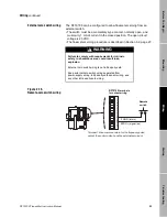
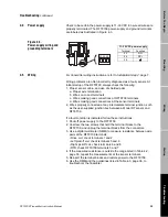
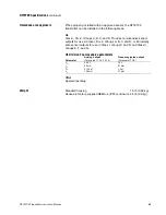
Figure 4-2. ProLink
®
PC-Interface connections
1. If necessary, add resistance in the loop by installing resistor R1. SMART FAMILY devices require a minimum loop
resistance of 250 ohms. Loop resistance must not exceed 1000 ohms, regardless of the communication setup.
2. The DCS or PLC must be configured for an active milliamp signal.
3. Resistor R3 is required if the DCS or PLC does not have an internal resistor.
CAUTION
If the primary variable (PV) analog output is being used for flow control, connecting the PC Interface
to the output loop could cause the transmitter 4-20 mA output to change, which would affect flow
control devices.
For personal and system safety, set control devices for manual operation before connecting the PC Interface to the
RFT9709 primary variable milliamp output loop.
RFT9709
HART (Bell 202)
loops
R2
R3
(Note 3)
R1
(Note 1)
DCS or PLC
with internal
resistor
(Note 2)
ProLink
®
PC Interface
HART
(Bell 202)
loops
PV+
PV–
PV terminals
11 and 12
11
12
or
09shoot.fm Page 34 Tuesday, March 2, 1999 9:26 AM
Summary of Contents for Fisher-Rosemount RFT9709
Page 1: ...Model RFT9709 Transmitter Instruction Manual March 1999 ...
Page 2: ......
Page 4: ......
Page 8: ...iv RFT9709 Transmitter Instruction Manual ...
Page 34: ...26 RFT9709 Transmitter Instruction Manual ...
Page 52: ...44 RFT9709 Transmitter Instruction Manual ...
Page 60: ...52 RFT9709 Transmitter Instruction Manual ...
Page 62: ...54 RFT9709 Transmitter Instruction Manual ...
Page 72: ...64 RFT9709 Transmitter Instruction Manual ...
Page 73: ......


