32
RFT9709 Transmitter Instruction Manual
Troubleshooting
continued
4.2
Transmitter diagnostic
tools
In some situations, troubleshooting requires use of the transmitter's
diagnostic tools, which include the diagnostic LED and fault output
levels.
Diagnostic LED
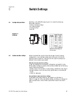
• Transmitter operating conditions indicated by the diagnostic LED are
listed in Table 4-1.
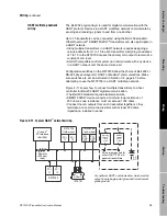
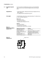
• The diagnostic LED is illustrated in Figure 4-1.
Fault outputs
The RFT9709 has downscale and upscale fault levels. To set fault levels,
see
Switch Settings
, Appendix C.
Downscale
Under fault conditions:
• mA outputs go to 0-2 mA
• frequency/pulse output goes to 0 Hz
Upscale
Under fault conditions:
• mA outputs go to 22-24 mA
• frequency/pulse output goes to 15-19 kHz
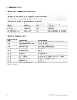
Table 4-1.
Conditions indicated by
diagnostic LED
Figure 4-1.
Diagnostic LED
Diagnostic LED does this:
Condition
Blinks ON once per second
(25% ON, 75% OFF)
Normal operation
Remains ON continuously
Startup and initialization, zero in progress
Blinks ON three times, then OFF
for 1 second
Communication configuration mode
(configuration switch 8 in ON position)
Blinks OFF once per second
(75% ON, 25% OFF)
Slug flow (density below or above user-
defined limits)
Blinks ON 4 times per second
Fault condition
Diagnostic LED
09shoot.fm Page 32 Tuesday, March 2, 1999 9:26 AM
Summary of Contents for Fisher-Rosemount RFT9709
Page 1: ...Model RFT9709 Transmitter Instruction Manual March 1999 ...
Page 2: ......
Page 4: ......
Page 8: ...iv RFT9709 Transmitter Instruction Manual ...
Page 34: ...26 RFT9709 Transmitter Instruction Manual ...
Page 52: ...44 RFT9709 Transmitter Instruction Manual ...
Page 60: ...52 RFT9709 Transmitter Instruction Manual ...
Page 62: ...54 RFT9709 Transmitter Instruction Manual ...
Page 72: ...64 RFT9709 Transmitter Instruction Manual ...
Page 73: ......


