background image

RFT9709 Transmitter Instruction Manual

49

Switch Settings


continued

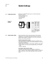
C.3

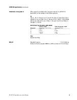
Fault output settings

Fault outputs can be set for downscale or upscale levels.

Downscale
If switch 7 is set to the DWN position:
• mA outputs go to 0-2 mA
• frequency/pulse output goes to 0 Hz

Upscale
If switch 7 is set to the UP position
• mA outputs go to 22-24 mA
• frequency/pulse output goes to 15-19 kHz

C.4

Security modes

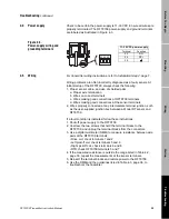
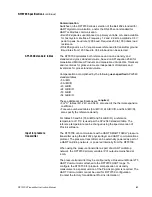
Switches 1, 2, and 3 are security switches, which enable the user to 
disable flowmeter zeroing, disable resetting of totalizers, and write-
protect all configuration and calibration parameters. Switch settings 
enable any of eight possible security modes. See Table C-2.
• Security modes 1 through 7 are entered immediately when switches 

1 through 3 are set.

• For information about security mode 8, see pages 50 and 51.

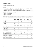
Table C-2. Security modes

Switch settings

Mode

1

Mode

2

Mode

3

Mode

4

Mode

5

Mode

6

Mode

7

Mode

8*

*Security mode 8 is not entered when switches are set. For more information about security mode 8, see pages 50 through 51.

Switch 1
Switch 2
Switch 3

OFF
OFF
OFF

OFF
OFF

ON

OFF

ON

OFF

OFF

ON
ON

ON

OFF
OFF

ON

OFF

ON

ON
ON

OFF

ON
ON
ON

Function/
parameter

Mode

1

Mode

2

Mode

3

Mode

4

Mode

5

Mode

6

Mode

7

Mode

8

Zeroing with zero button

Disabled

Disabled

Disabled

Disabled

Disabled

Disabled

Disabled

Zeroing with digital 
communication

Disabled

Disabled

Disabled

Disabled

Totalizer reset, no flow

Disabled

Disabled

Disabled

Totalizer reset, with flow

Disabled

Disabled

Disabled

Disabled

Disabled

Disabled

Configuration and 
calibration parameters

Write-

protected

Write-

protected

Write-

protected

Write-

protected

Write-

protected

Write-

protected

09switch.fm  Page 49  Tuesday, March 2, 1999  9:36 AM

Summary of Contents for Fisher-Rosemount RFT9709

Page 1: ...Model RFT9709 Transmitter Instruction Manual March 1999 ...

Page 2: ......

Page 3: ... 549 443 In Asia phone 65 770 8155 Copyright 1999 Micro Motion Inc All rights reserved Micro Motion ELITE BASIS and ProLink are registered trademarks of Micro Motion Inc Boulder Colorado Rosemount and SMART FAMILY are registered trademarks of Rosemount Inc Eden Prairie Minnesota HART is a registered trademark of the HART Communication Foundation Austin Texas Modbus is a registered trademark of Mod...

Page 4: ......

Page 5: ...neral guidelines 7 2 2 Power supply wiring and grounding 8 2 3 Sensor wiring 9 Cable types 10 Remotely installed temperature detector 11 Cable connections to sensor and RFT9709 12 2 4 Output wiring 17 Primary and secondary mA outputs 18 HART multidrop network wiring 19 RS 485 output 20 Frequency pulse output 21 Control output 22 External zero switch wiring 23 Viscosity measurement or pressure comp...

Page 6: ... the ProLink program 33 Output test and trim 33 4 4 Power supply 35 4 5 Wiring 35 4 6 Master reset 37 4 7 Customer service 37 Appendixes Appendix A RFT9709 Specifications 39 Appendix B Ordering Information 45 Appendix C Switch Settings 47 Appendix D Open Collector Configuration 53 Appendix E Decontamination and Return Goods Policy USA 55 Appendix F Decontamination and Return Goods Policy Europe 57...

Page 7: ... wiring and grounding connections 8 Figure 2 3 Cable types 10 Figure 2 4 Terminating flowmeter cable 10 Figure 2 5 RFT9709 terminals for sensor wiring 13 Figure 2 6 Wiring to ELITE CMF sensors 14 Figure 2 7 Wiring to BASIS F Model D and DL sensors 15 Figure 2 8 Wiring to Model DT sensors 16 Figure 2 9 Terminating output wiring shields and drains 17 Figure 2 10 mA output terminals 18 Figure 2 11 Ty...

Page 8: ...iv RFT9709 Transmitter Instruction Manual ...

Page 9: ...rovide any of three standard configuration options Gross volume API table 5A Gross standard volume API table 5A Not configured For specific configuration details see the calibration certificate that is shipped with the sensor To meet API requirements the user must supply an external RTD that is accurate to 0 1 F The external RTD calibration must be configured in the transmitter The factory can con...

Page 10: ... information contact the Micro Motion Customer Service Department In the U S A phone 1 800 522 MASS 1 800 522 6277 Outside the U S A phone 303 530 8400 In Europe phone 31 0 318 549 443 In Asia phone 65 770 8155 RFT9709 components Output wiring connector Mounting boss Channel for routing sensor cable Power supply wiring terminals Sensor cable wiring connector Mounting boss Configuration switches Ze...

Page 11: ... described below Hazardous area installations Read the RFT9709 approvals tag before installing the transmitter The approvals tag is attached to the RFT9709 housing See Figure 1 1 For a complete list of approvals see Hazardous area approvals page 43 For an intrinsically safe or hazardous area installation use this manual with Micro Motion UL D IS Installation Instructions Figure 1 1 RFT9709 approva...

Page 12: ...nclosure Install the RFT9709 with two screws to a flat mounting surface Micro Motion does not supply mounting screws Install with wiring terminals facing away from the mounting surface RFT9709 dimensions are provided in Figure 1 2 Figure 1 2 RFT9709 dimensions 1 13 16 46 Dimensions in inches mm 1 11 32 34 3 5 32 80 Mounting boss Use 8 32 M4 screws with flat washers and lock washers for mounting 2X...

Page 13: ...ge 4 Conduit openings Whether the optional NEMA housing is supplied by the user or the factory the user must add three conduit openings for power supply wiring input wiring and output wiring Locate the housing so these openings are accessible for installation of wiring and so the housing cover can be fully opened for access to the RFT9709 inside To help prevent moisture from entering the housing i...

Page 14: ...10 7 16 266 2X 7 3 16 183 Minimum clearance to open access cover 11 7 8 301 9 11 16 247 2X 7 11 16 196 2X 11 11 16 297 5 11 16 145 2X 8 7 16 215 2X 0 31 8 4X Ø 1 4 6 2X 1 3 8 35 4X 4X 5 16 18 UNC flat head screw for mounting feet included cover access screw 2X Cover hinge Housing requires installation of three conduit openings for power supply wiring input wiring and output wiring Recommended open...

Page 15: ...uirements For an RFT9709 installed in a NEMA enclosure The RFT9709 may be installed in a user supplied or factory supplied NEMA 4 IP65 enclosure as described in Section 1 4 page 5 The enclosure requires three separate conduit openings for power supply wiring sensor wiring and output wiring Conduit openings must remain sealed to maintain the NEMA 4 IP65 rating Use conduit seals or cable glands that...

Page 16: ...wer supply wiring separated from intrinsically safe sensor wiring and output wiring For intrinsically safe sensor installations use this document with Micro Motion UL installation instructions CAUTION Installation with power supply on could cause transmitter damage or failure Turn off power before connecting power supply wiring 11 30 VDC power supply Terminal Function 23 DC 24 DC 25 6 32 ground nu...

Page 17: ...uirements Use Micro Motion color coded cable Total length of cable from the sensor to the RFT9709 must not exceed 1000 feet 300 meters WARNING Failure to comply with requirements for intrinsic safety in a hazardous area could result in an explosion Sensor wiring is intrinsically safe Keep intrinsically safe sensor wiring separated from power supply wiring and output wiring For intrinsically safe s...

Page 18: ...xtend under the wiring terminals access cover as illustrated in Figure 2 4 Shielded and armored cable must have the braided shield terminated as illustrated in Figure 2 4 Figure 2 3 Cable types Figure 2 4 Terminating flowmeter cable Braided shield Jacketed cable Shielded or armored cable Jacket Outer jacket Jacket For shielded or armored flowmeter cable connect braided shield at mounting boss Jack...

Page 19: ...xternal temperature detector Locate the external temperature detector as close to the sensor as possible Use an individually shielded 3 wire cable of 22 AWG 0 3 mm or larger wires to connect the external temperature detector to the flowmeter Wiring diagrams are provided in Figure 2 6 Figure 2 7 and Figure 2 8 on pages 14 through16 Procedure for installing the user supplied external temperature det...

Page 20: ...ust extend under the RFT9709 wiring terminals access cover For easier connection of wiring terminal blocks can be unplugged from the RFT9709 Two captive screws hold each terminal block in place 2 Locate the wires by color as indicated in Table 2 1 3 Tighten the screws to hold the wires in place 4 Tightly close all housing covers Tighten the sensor junction box cover Tighten all four cover screws C...

Page 21: ...mperature Right pickoff Left pickoff Combined drain wires Wire color Sensor terminal RFT9709 terminal Function Black Combined drain wires from brown red green white and gray blue pairs and yellow orange violet triplet Cut off drain wires and protect from shorting to any metal or terminals No connection 0 Drain wires Brown 1 1 Drive Red 2 2 Drive Orange 3 3 Temperature Yellow 4 4 Temperature return...

Page 22: ...rdance with the instructions that are shipped with the cable RFT9709 terminals Optional remote temperature detector RTD wiring required for API ELITE sensor terminals No connection 1 In the sensor junction box identify the violet yellow and orange wires that come from the sensor 2 Disconnect these wires from the terminal block then tie all three together with a wire nut to protect exposed wire end...

Page 23: ...on BASIS Model D or DL sensor terminals No connection D600 sensor terminals 1 In the sensor junction box identify the violet yellow and orange wires that come from inside the sensor 2 Disconnect these wires from the terminal block then tie all three together with a wire nut to protect exposed wire ends 3 Connect three wires from the external RTD to the terminals from Step 2 as illustrated above If...

Page 24: ...r User supplied metal junction box with terminal block Earth ground Optional remote temperature detector RTD wiring required for API 1 In the sensor junction box identify the violet yellow and orange wires that come from the sensor 2 Disconnect these wires from the terminal block then tie all three together with a wire nut to protect exposed wire ends 3 Connect three wires from the external RTD to...

Page 25: ...igure 2 9 or at the peripheral device Table 2 2 Output wiring terminal designations Figure 2 9 Terminating output wiring shields and drains WARNING Failure to comply with requirements for intrinsic safety in a hazardous area could result in an explosion Output wiring is not intrinsically safe Keep output wiring separated from power supply wiring and intrinsically safe sensor wiring Follow all outp...

Page 26: ...by measuring resistance over the signal wires and through the receiver device Total loop resistance must not exceed 1000 ohms Output fault setting The mA outputs can be set to produce downscale or upscale fault levels If set to downscale switch 7 off a fault drives the outputs to 0 2 mA If set to upscale switch 7 on a fault drives the outputs to 22 24 mA Low flow cutoffs If an mA output is configu...

Page 27: ...he choice of Bell 202 or RS 485 physical layers for HART or Modbus communications Make sure switches are set as instructed in Section C 2 page 47 before attempting to use the RFT9709 in a HART multidrop network Figure 2 11 shows how to connect multiple transmitters to a host controller for Bell 202 HART digital communication The Bell 202 standard requires twisted pair wire SMART FAMILY devices req...

Page 28: ...ting to use the RFT9709 in an RS 485 multidrop network Figure 2 12 shows how to connect one transmitter or multiple transmitters to a host controller for RS 485 serial communication Install twisted pair shielded cable consisting of 24 AWG 0 25 mm or larger wire between the RFT9709 and an RS 485 communication device Maximum cable length is 4000 feet 1200 meters Some installations require a 120 ohm ...

Page 29: ...d Any load will decrease the peak voltage level Output impedance is 3 3 kohm The frequency pulse output loop is isolated and floating Additional grounding will result in optimum performance Ensure that the frequency pulse output loop is grounded at the external device If necessary the frequency output can be configured for open collector mode For instructions see Appendix D page 53 When used in th...

Page 30: ...utput is low 0 V when zeroing is in progress and high 23 V at all other times When configured to indicate faults the output is low 0 V when a fault condition exists and high 23 V during normal operation When configured to indicate event 1 or event 2 the output switches ON 0 V or OFF 23 V when the flow rate flow total density temperature pressure or viscosity of the process fluid achieves a program...

Page 31: ...s described in Section 3 2 page 27 Figure 2 15 Remote zero switch wiring WARNING Failure to comply with requirements for intrinsic safety in a hazardous area could result in an explosion External zero switch wiring is not intrinsically safe Keep external zero switch wiring separated from power supply wiring intrinsically safe sensor wiring and any other intrinsically safe wiring RFT9709 terminals ...

Page 32: ...ter requirements The pressure transmitter must be a HART SMART FAMILY device The pressure transmitter can be powered from the RFT9709 or externally powered as part of a HART multidrop network See HART multidrop network wiring page 19 Multidrop network requirements The pressure transmitter must be assigned a unique multidrop address from 1 to 15 The RFT9709 must be assigned a unique multidrop addre...

Page 33: ...ure to comply with requirements for intrinsic safety in a hazardous area could result in an explosion Pressure transmitter wiring is not intrinsically safe Keep pressure transmitter wiring separated from power supply wiring intrinsically safe sensor wiring and any other intrinsically safe wiring Pressure transmitter SMART only 1151 or 3051 RFT9709 terminals for output wiring 11 12 13 14 15 16 17 1...

Page 34: ...26 RFT9709 Transmitter Instruction Manual ...

Page 35: ...shes flowmeter response to zero flow and sets a baseline for flow measurement Zeroing is necessary when the flowmeter is first put into operation and if either the transmitter or sensor is replaced or reinstalled Zeroing is not necessary every time power is applied to the transmitter or when a new process fluid is run through the sensor Zeroing is accomplished with the RFT9709 zero button see Figu...

Page 36: ... used for zeroing Close the contact for at least 5 seconds Refer to External zero switch wiring page 23 for wiring instructions Issue an auto zero command using a special version of the ProLink program The HART Communicator cannot be used for zeroing the flowmeter Contact the factory for additional ProLink information During zeroing the diagnostic LED remains on continuously The default zero time ...

Page 37: ...ster counts up to 999 then rolls over to zero Event registers cannot be reset Event registers can be read using a special version of the ProLink program The HART Communicator cannot be used for viewing these registers Contact the factory for additional ProLink information Table 3 1 Parameters that affect event registers Configuration register Mass flow cutoff Flow damping Volume flow cutoff Flow d...

Page 38: ... for additional ProLink information 3 5 Process measurement After flowmeter zeroing has been completed as described in Section 3 2 page 27 the flowmeter is ready for process measurement WARNING When the totalizers are stopped the frequency pulse output is disabled If the frequency pulse output is used for process control failure to set control devices for manual operation could affect process cont...

Page 39: ...ith this instruction manual and with the instruction manual for the sensor While troubleshooting a problem leave the sensor in place if possible Problems often result from the specific environment in which the sensor operates Check all signals under both flow and no flow conditions This procedure will minimize the possibility of overlooking some causes or symptoms CAUTION During troubleshooting th...

Page 40: ...Appendix C Downscale Under fault conditions mA outputs go to 0 2 mA frequency pulse output goes to 0 Hz Upscale Under fault conditions mA outputs go to 22 24 mA frequency pulse output goes to 15 19 kHz Table 4 1 Conditions indicated by diagnostic LED Figure 4 1 Diagnostic LED Diagnostic LED does this Condition Blinks ON once per second 25 ON 75 OFF Normal operation Remains ON continuously Startup ...

Page 41: ...FT9709 runs continuous self diagnostic tests If these tests reveal a failure the ProLink program displays an error message Self testing allows the RFT9709 to check its own circuitry Output test and trim The RFT9709 works with a Micro Motion flow sensor to provide flow information Therefore many of the troubleshooting checks pertain only to the sensor However the ProLink program enables the user to...

Page 42: ...required if the DCS or PLC does not have an internal resistor CAUTION If the primary variable PV analog output is being used for flow control connecting the PC Interface to the output loop could cause the transmitter 4 20 mA output to change which would affect flow control devices For personal and system safety set control devices for manual operation before connecting the PC Interface to the RFT9...

Page 43: ...he sensor terminals 2 Wires properly connected at any intermediate terminal junction such as the user supplied junction box between a Model DT sensor and RFT9709 If a fault condition is indicated follow these instructions 1 Shut off power supply to the RFT9709 2 Unscrew the two screws that hold the terminal blocks to the RFT9709 and unplug the terminal blocks from the connectors 3 Use a digital mu...

Page 44: ... 35 to 175Ω depending on process fluid Lead Length Compensator Yellow to Violet 4 to 7 35 to 175Ω depending on process fluid Transmitter terminal number Input or output Approximate value 1 to 2 Drive signal output to sensor 1 2 to 14 V peak to peak at flow tube natural frequency 3 to 4 Lead length compensator input 10 mVDC maximum 5 to 9 Left pickoff input 3 4 mV Hz peak to peak sine wave 6 to 8 R...

Page 45: ...sition configure communications as described in Communication settings page 47 9 Reconfigure the transmitter A special version of the ProLink software program is required for field configuration Contact the factory for ProLink information To avoid an unintentional master reset set switches 4 6 and 8 to the OFF position after performing a master reset If switches are left in the ON position another...

Page 46: ...ff 0 0000 l sec High slug flow limit 5 0000 g cc Flow direction Forward only Internal damping on density 2 00 sec Internal damping on flow 0 80 sec Internal damping on temperature 4 00 sec Transmitter output variables Default Default Primary mA output variable Mass flow Frequency pulse output variable Mass flow Upper range value 160 00 g sec Frequency 10000 00 Hz Lower range value 160 00 g sec Rat...

Page 47: ...0 25 zero stability flow rate x 100 of rate Sensor model Density accuracy Density repeatability ELITE except high pressure CMF010P liquid gas 0 0005 g cc 0 002 g cc 0 0002 g cc 0 001 g cc ELITE high pressure CMF010P liquid gas 0 002 g cc 0 008 g cc 0 001 g cc 0 004 g cc BASIS liquid only 0 002 g cc 0 001 g cc D6 D12 D25 D40 DH100 DH150 liquid only 0 002 g cc 0 001 g cc DH6 DH12 DH38 liquid only 0 ...

Page 48: ...imum span Temperature 400 to 842 F 240 to 450 C range limit 36 F 20 C minimum span Frequency pulse One frequency pulse output can be configured to indicate mass mass flow rate gross volume flow rate gross standard volume flow rate or gross standard volume independent of analog outputs Internally powered 0 23 V square wave unloaded 3 3 kohm impedance at 23 V galvanically isolated to 50 VDC In open ...

Page 49: ...D 53 A B D 54 A B C D These additional specifications are required For C tables 6C 24C and 54C also specify the thermal expansion coefficient For even numbered tables 6 A B C D 24 A B C D and 54 A B C D also specify the reference density For tables 53 and 54 53 A B D and 54 A B C D a reference temperature of 15 C is used per the API 2540 standard table The reference temperature can be changed usin...

Page 50: ...utput levels The control output can also be configured to indicate a fault condition at 0 V Output testing Current source RFT9709 can produce a user specified current between 2 and 22 mA on a 4 20 mA output Frequency source RFT9709 can produce a user specified frequency between 0 1 and 15 000 Hz Power supply options 11 to 30 VDC 7 watts typical 14 watts maximum fused with IEC 127 3 1 6A 125V time ...

Page 51: ...sensor outputs for use in Class I Div 2 Groups A B C and D or intrinsically safe sensor outputs for use in Class I Groups C and D and Class II Groups E F and G UL Division 2 nonincendive parameters CSA Approval pending Weight Standard housing 1 5 lb 0 68 kg Housed in factory supplied NEMA 4 IP65 enclosure 6 5 lb 2 9 kg Parameter Analog output Terminals 11 12 13 14 Frequency pulse output Terminals ...

Page 52: ...44 RFT9709 Transmitter Instruction Manual ...

Page 53: ...odel RFT9709 RFT9709 transmitter Code Housing options S Standard N Optional factory supplied NEMA 4 IP65 enclosure Code Power supply 1 11 to 30 VDC Code Connector options C Terminal block connections all connectors included Code Approval M Micro Motion standard no approvals U UL intrinsically safe U S A approvals agency ...

Page 54: ...rol Applications Manual ALTUS HFCS Brix Applications Manual ALTUS Net Oil Computer Applications Manual Installing Relays for the ALTUS Applications Platform Printer Setup for the ALTUS Applications Platform Communications Using ProLink Software with Micro Motion Transmitters Using the HART Communicator with Micro Motion Transmitters Using Modbus Protocol with the Micro Motion ELITE Model RFT9739 T...

Page 55: ...ion setting To use the standard communication configuration set switch 5 to the STD position Setting the switch in this position establishes the following communication parameters HART protocol at 1200 baud on the primary variable PV mA output Modbus protocol in RTU mode 8 bit at 9600 baud on the RS 485 output 1 stop bit odd parity User defined communication settings To establish user defined sett...

Page 56: ...and 8 are left in the ON position after configuration a master reset will occur the next time power to the RFT9709 is shut off and then restored To avoid an unexpected master reset make sure switches 4 6 and 8 are left in the OFF position after configuration Baud rate Switch 1 Switch 2 Switch 3 Switch 4 Switch 5 Switch 6 1200 baud ON ON 2400 baud ON ON ON 4800 baud ON ON 9600 baud ON ON ON 19 200 ...

Page 57: ...tches 1 through 3 are set For information about security mode 8 see pages 50 and 51 Table C 2 Security modes Switch settings Mode 1 Mode 2 Mode 3 Mode 4 Mode 5 Mode 6 Mode 7 Mode 8 Security mode 8 is not entered when switches are set For more information about security mode 8 see pages 50 through 51 Switch 1 Switch 2 Switch 3 OFF OFF OFF OFF OFF ON OFF ON OFF OFF ON ON ON OFF OFF ON OFF ON ON ON O...

Page 58: ...has been performed Custody transfer event registers are not affected by a master reset Before entering security mode 8 perform milliamp trim and or test procedures if necessary Milliamp output trim milliamp output test and frequency pulse output test cannot be performed after security mode 8 is entered A special version of the ProLink program is required to perform these procedures A HART Communic...

Page 59: ...d configuration and calibration parameters see Section 3 3 page 29 3 Set switches 1 2 and 3 to the ON position To reenter security mode 8 If security mode 8 has been established previously and the security mode has been temporarily changed it is not necessary to use the zero button to reenter security mode 8 In such a case resetting switches 1 2 and 3 to the ON position will reenter security mode ...

Page 60: ...52 RFT9709 Transmitter Instruction Manual ...

Page 61: ...or open collector mode jumpers on the RFT9709 must be cut Refer to Figure D 1 Figure D 1 Configuring open collector mode CAUTION The open collector configuration procedure cannot be reversed Configuring the frequency pulse or control outputs for open collector mode requires jumpers on the RFT9709 to be cut Once cut the jumpers cannot be reconnected Do not cut jumpers unless you are certain your pr...

Page 62: ...54 RFT9709 Transmitter Instruction Manual ...

Page 63: ...from the case interior To avoid risk of explosion do not drill the case if a combustible gas may be present The flow tubes must be cleaned and decontaminated of all foreign substances Shipping equipment that has not been decontaminated may violate DOT regulations The requirements for packaging and labeling hazardous substances are listed in DOT regulations 49 CFR 172 178 and 179 A DECONTAMINATION ...

Page 64: ...ted on the shipping package Two copies of this DECONTAMINATION CLEANING STATEMENT and Material Safety Data Sheet MSDS if required must be included one attached to the outside of the box and one inside of the shipping package Ship equipment to Micro Motion Inc 6930 Winchester Circle Dock 6 Attn RMA ________ Boulder CO 80301 Refer to Micro Motion Equipment Return Requirements page 55 I hereby certif...

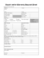
Page 65: ...fying you of the contamination 1 The equipment must be COMPLETELY cleaned and decontaminated prior to shipment to Rosemount This decontamination procedure applies to the sensor tubes sensor case exterior and the transmitter 2 A Repair and or Warranty Request Sheet RWRS is REQUIRED for all process fluids that have been in contact with the equipment This includes fluids used to clean the equipment 3...

Page 66: ...y Sensor condition Process conditions Tubes empty yes no Medium Case empty yes no Chemical formula Decontamination statement yes no Maximum temperature Type of cleaning material used Operating pressure Warning For the health and safety of our goods handling inspection department a Decontamination Statement MUST be filled in with this form Please be specific with the information provided Calibratio...

Page 67: ... sensor See Sensor Wiring Communication See also HART Modbus ProLink program configuration 48 master reset default values 38 using switches 47 output specification 41 Conduit general wiring guidelines 8 openings in NEMA IP65 housing 5 sensor wiring 9 wiring guidelines 7 Configuration 1 master reset default values 38 pressure transmitter 24 security modes 49 51 Configuration switches 47 51 47 Bell ...

Page 68: ...tor See HART protocol ProLink program HART protocol See also ProLink program Bell 202 multidrop network 19 communication configuration 48 configuration and calibration 1 configuration switches 47 mA outputs 18 master reset 37 master reset default values 38 pressure transmitter input specification 41 RS 485 output 20 specifications communication output 41 pressure transmitter 41 Hazardous areas See...

Page 69: ...llector configuration 53 53 Open collector mode frequency pulse output 21 22 Ordering information 45 46 OSHA See Return goods policy Outputs control 22 open collector configuration 53 53 output performance 22 specification 40 fault indication 32 frequency pulse 21 22 open collector configuration 53 53 open collector mode 21 22 performance and requirements 21 security mode 8 50 specification 40 tes...

Page 70: ...See Return Goods Policy RS 485 communication configuration 48 communication output specification 41 configuration switches 47 multidrop network 20 wiring 20 RTD installing 11 remote wiring DT sensors 16 ELITE sensors 14 15 procedure 11 requirements 11 RTU mode See Modbus protocol RWRS See Return goods policy S Secondary output 18 See also mA output Security breach 50 configuration switches 47 even...

Page 71: ...ing 8 Upscale configuration switches 49 fault indication 32 42 V Vibration limits 42 Viscosity measurement 24 W Weight 43 Wiring 7 25 Bell 202 multidrop network 19 cable types 10 10 connections to sensor and transmitter 12 faulty See Troubleshooting general guidelines 7 grounding 8 8 instruction manuals 46 IP65 housing requirements 5 NEMA housing requirements 5 outputs 17 25 Bell 202 multidrop net...

Page 72: ...64 RFT9709 Transmitter Instruction Manual ...

Page 73: ......

Page 74: ...530 8459 Micro Motion Europe Groeneveldselaan 6 3903 AZ Veenendaal The Netherlands Tel 31 0 318 549 549 Fax 31 0 318 549 559 Micro Motion Asia 1 Pandan Crescent Singapore 128461 Republic of Singapore Tel 65 777 8211 Fax 65 770 8003 Visit us on the Internet at www micromotion com 1999 Micro Motion Inc All rights reserved P N 3003091 Rev A 3 99 ...

Reviews: