RFT9709 Transmitter Instruction Manual
13
Wiring
continued
Wirin
g
Sta
rt
up
T
roub
lesh
ootin
g
Bef
o
re
Y
ou Be
gin
Mou
n
ting
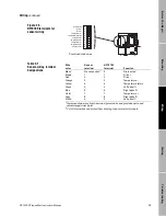
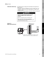
Figure 2-5.
RFT9709 terminals for
sensor wiring
Table 2-1.
Sensor-wiring terminal
designations
9 8 7 6 5 4 3 2 1 0
Drain wires
Drive +
Drive –
Temperature –
Temperature return
Left p
Right p
Tempe
Right pickoff –
Left pickoff –
*
*Combined drain wires.
Wire
color
Sensor
terminal
RFT9709
terminal
Function
Black*
*Combined drain wires from brown/red, green/white, and gray/blue pairs, and
yellow/orange/violet triplet.
**Cut off drain wires and protect from shorting to any metal or terminals.
No connection**
0
Drain wires*
Brown
1
1
Drive +
Red
2
2
Drive –
Orange
3
3
Temperature –
Yellow
4
4
Temperature return
Green
5
5
Left p
Blue
6
6
Right p
Violet
7
7
Tempe
Gray
8
8
Right pickoff –
White
9
9
Left pickoff –
09wire.fm Page 13 Monday, March 1, 1999 4:31 PM
Summary of Contents for Fisher-Rosemount RFT9709
Page 1: ...Model RFT9709 Transmitter Instruction Manual March 1999 ...
Page 2: ......
Page 4: ......
Page 8: ...iv RFT9709 Transmitter Instruction Manual ...
Page 34: ...26 RFT9709 Transmitter Instruction Manual ...
Page 52: ...44 RFT9709 Transmitter Instruction Manual ...
Page 60: ...52 RFT9709 Transmitter Instruction Manual ...
Page 62: ...54 RFT9709 Transmitter Instruction Manual ...
Page 72: ...64 RFT9709 Transmitter Instruction Manual ...
Page 73: ......

