Autolab/Electronic load combination
23 |
P a g e
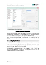
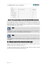
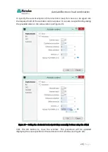
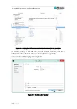
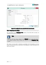
Figure 15 – The conversion settings for the Kikusui PLZ164WA electronic load
These settings indicate that the analog signal provided by the Kikusui electronic
load, in V, need to be multiplied by -3.3 in order to be converted into current, with
the correct polarity.
9.2
– Analog output settings
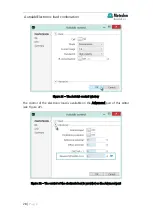
In the DAC164 – 1 section, the conversion settings control the current setpoint of
the electronic load can be defined and saved for future use. The settings depend
on the type of load. Please refer to the electronic load user manual for more
information.
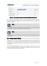
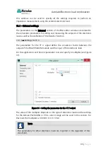
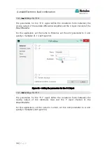
For the Kikusui PLZ164WA load, used in the examples in Section 8.3.2 of this
manual, the settings required to convert the analog signal from the load into the
correct current value are shown in Figure 16.
Note
It is possible to save these settings in the Hardware setup for future use by
clicking the button on the right-hand side of this panel.
Note
The parameters for other electronic loads are reported in the Appendix of this
document.

