Autolab/Electronic load combination
17 |
P a g e
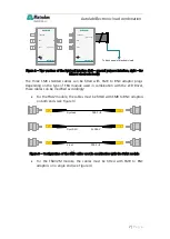
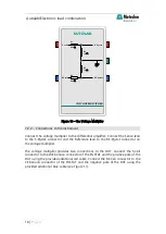
Figure 11 – Wiring diagram of the voltage multiplier between the DUT and the PGSTAT
8
– Electronic load settings
Before the measurements can be performed, it is mandatory to program the
electronic load. Please refer to the user manual provided with the electronic load
for more information or contact Metrohm Autolab B.V. for setup guidelines
(
).
Most electronic loads have a number of common settings which have to be
considered:
•
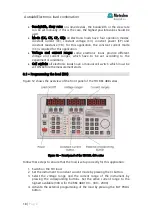
External control (ON/OFF): all electronic loads have a switch which
activates or deactivates the external programming capability. This switch
must be set to ON.
+
-
Differential amplifier
S
RE
GND
S
RE
+
-
Voltage multiplier
Differential amplifier
S
RE
GND
S
RE
Warning
Connect the green ground cable from the PGSTAT to the GND connector on
the voltage multiplier! The ground cable must be connected to the voltage
multiplier at all times.


