background image

M ET E K  

M ic r o   R a i n   R a d a r   M R R - 2


21


10.2010 Valid for MRR Service Version ≥ 5.2.0.9


6.2.1  Main Menu 


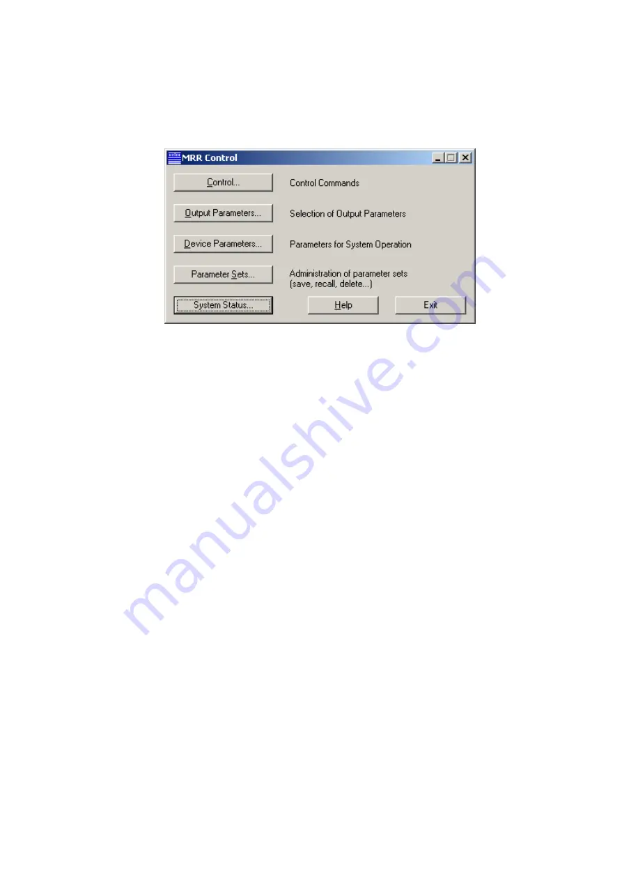
Figure 10: Main Menu


The main menu shows buttons for the menus 

Control


chapter 6.2.2 on page 22


Output Parameters


chapter 6.2.3 on page 22 

Device Parameters


chapter 6.2.4 on page 25


Parameter Sets


chapter 6.2.5 on page 27 

System Status


chapter 6.2.6 on page 29 

You can leave the program with the 

Exit

 button. 

The 

Help

 button provides a Windows conforming help text. 


Summary of Contents for MRR-2

Page 1: ...10 2010 Valid for MRR Service Version 5 2 0 9 MRR 2 Micro Rain RADAR User Manual...

Page 2: ...e mail info metek de internet http www metek de Copyright 2010 METEK GmbH All Rights reserved No part of this manual may be reproduced transmitted stored in a retrieval system nor translated into any...

Page 3: ...5 Cable RCPD Junction Box 13 4 2 6 Cable Junction Box PC 13 4 2 7 Control and Evaluation Computer PC 14 5 Hardware Installation 15 5 1 General Provisions 15 5 2 Site Conditions 15 5 3 Installation Pro...

Page 4: ...e 40 6 5 Removing of the Software 41 7 Detailed description of the MRR 2 control program 41 7 1 Communication Data and Error Service CDES 42 7 1 1 Communication Service 42 7 1 2 Data Recording 42 7 1...

Page 5: ...am above the antenna parabolic dish when it is in operation All connecting cables plugs and couplings of the MRR 2 are not inter changeable to prevent any erroneous assembly This safety precaution is...

Page 6: ......

Page 7: ...t section 5 for setting up the hardware In section 6 the installation and use of the control software is de scribed The technical specifications are listed in section 8 Section 7 contains more detaile...

Page 8: ...is of the received signal yields a power spectrum which is spread over a range of frequencies lines corresponding to the Doppler fre quencies of the signal The RCPD determines this power spectrum with...

Page 9: ...METEK Micro Rain Radar MRR 2 7 10 2010 Valid for MRR Service Version 5 2 0 9 4 System Description 4 1 Overview...

Page 10: ...r MRR Service Version 5 2 0 9 Figure 1 Components of the System 1 Parabolic Dish 2 Transceiver 3 RCPD 4 Junction Box 5 Cable Junction Box PC 6 AC Power Cable 7 Cable RCPD Junction Box 8 Antenna Arm 9...

Page 11: ...010 Valid for MRR Service Version 5 2 0 9 The Control and Evaluation Computer a commercial PC not part of delivery must be ordered separately The operating system must be Windows 2000 or XP Windows Vi...

Page 12: ...e moved in its pivot 9 because this would cause beam deviations from vertical and would result in erroneous measurements The transmitting and receiving properties of the antenna affect the radar cali...

Page 13: ...lculates Doppler spectra and transfers average power spectra re ferred to as raw da ta to the control and evaluation PC where these spectra are in terpreted The RCPD is located in a water protected IP...

Page 14: ...the PC and a flanged socket 17 for the cable 7 to the RADAR RCPD 3 The power supply for the RCPD and Transceiver is also integrated in the junc tion box An IEC connector for the mains supply of 230 V...

Page 15: ...5 m on both ends are screwed plugs male and female respectively They must be screwed onto the matching plugs at the junction box cable has pins and at the RCPD cable has sockets 4 2 6 Cable Junction B...

Page 16: ...t supported The PC must have at least one serial port which will be configured by the con trol program as follows 57600 baud 8 data bits no parity software protocol XON XOFF no hardware protocol hands...

Page 17: ...s There must be free view of at least 10 zenith angle over the radar Nearby transmitters base stations of mobile phones broadcast towers ra dars can cause interference although they operate nominally...

Page 18: ...fixed vertical pole max 49 mm length min 30 cm is required for attach ing the antenna Operating of the MRR 2 requires a 230 VAC mains supply with a fuse protection of 8 A slow minimum To prevent distu...

Page 19: ...ing protection 5 Connect cable 7 between RCPD and Junction Box after mounting of the antenna 6 Connect cable 5 to that serial interface of the computer which was se lected in the operating system for...

Page 20: ...Activate the install menu The files are copied and the registry of the PC is updated When the copy process has finished reboot the PC Note The data flow rate from the MRR to the PC requires that the P...

Page 21: ...ally see the header of the dialog window The network connection to the remote computer usually is a LAN or a RAS connection RAS connections using the public telephone net are mostly not very efficient...

Page 22: ...nication service could be built up the entire status of the MRR 2 is read out first This can take some seconds on RAS connections even some minutes Click the OK button The MRR 2 status is read out whi...

Page 23: ...shows buttons for the menus Control chapter 6 2 2 on page 22 Output Parameters chapter 6 2 3 on page 22 Device Parameters chapter 6 2 4 on page 25 Parameter Sets chapter 6 2 5 on page 27 System Status...

Page 24: ...djust interval length to real time clock This checkbox activates the synchronization of measuring intervals to the ac tual time of day This means every output of averaged data will occur at round time...

Page 25: ...tion of causes the recording of Height2 Measuring height above ground Spectra Spectral volume reflectivity Drop Spectra Drop diameter and number of drops per vol ume and diameter Attenuation Two way p...

Page 26: ...of measuring heights can be selected for recording This subset is used for both kinds of data output instantaneous and averaged data The se lection of measuring heights for output is done with two li...

Page 27: ...data are generated and recorded independently in 10 s time intervals within each averaging interval Device Location ASL Enter the height of the MRR 2 location above sea level The adjustable range is...

Page 28: ...li bration constant new C can be calculated according MRR RG old new R R C C It should be kept in mind that comparisons of rain rates measured aloft with the MRR and a rain gauge are not straightforwa...

Page 29: ...rameter settings A parameter set consists of the device parameters except calibration constant and the selected output parameters Saving a parameter set Type a name in the field right of the Save butt...

Page 30: ...the next entry will be loaded from the list After reaching the end of this list the program starts over with the first entry Creating a Program List Select a parameter set in the Parameter Sets list...

Page 31: ...service program is shown The operation state is shown normal operation No problems occurred erroneous operation One component of the service could not be installed Either a hardware error or a conflic...

Page 32: ...alues This can be useful under the following condition If the Adjust interval length to real time clock see chapter 6 2 2 Control Com mands Menu was selected the time stamps should be integer multi pl...

Page 33: ...nsfer Function dimensionless Fnn Spectral Reflectivities dB 10 log nn with nn in m 1 nn from min h to max h 3 Dnn Drop Size mm Center of size class Nnn Spectral Drop Densities m 3 mm 1 N Dnn 3 PIA Pat...

Page 34: ...tantaneous data height resolution in meters STP height of the ground level above sea level in meters ASL sampling rate SMP of the RADAR signal in the time domain unit Hz parameters for the automatic n...

Page 35: ...Argument of the following data profiles corresponding to the settings described in chapter 6 2 3 page 22 and chapter 6 2 4 page 25 The units are meters above the radar system TF Transfer Function To e...

Page 36: ...max h depends on the height as described in MRR Physical Basics Fig 7 In case of negative values of Fnn negative drop number densities are calcu lated Although they have no physical meaning they are...

Page 37: ...ics The width of velocity bins can be derived from the maximum number of height steps the sampling rate as shown in the header line and the wave length of the RADAR signal 32 height steps and 64 lines...

Page 38: ...31 54 80 55 01 56 92 F27 63 97 63 27 63 33 64 91 64 92 64 37 63 66 64 41 64 32 64 00 64 29 64 24 64 95 64 87 64 77 65 51 66 43 67 06 67 47 67 73 68 02 67 71 66 55 65 37 64 70 62 52 59 00 56 22 54 55...

Page 39: ...1 9362 1 9317 1 9272 1 9228 D36 2 1713 2 1661 2 1608 2 1556 2 1504 2 1452 2 1400 2 1348 2 1296 2 1245 2 1193 2 1142 2 1091 2 1040 2 0989 2 0938 2 0888 2 0837 2 0787 2 0737 2 0686 2 0637 2 0587 2 0537...

Page 40: ...73 26 959 24 1050 9 1068 5 858 33 744 14 829 82 857 60 842 94 812 12 831 79 723 97 797 48 805 01 917 07 1012 8 1109 3 1210 2 1333 5 1407 9 1414 7 1116 5 712 05 366 94 154 27 62 599 17 781 2 8902 43 53...

Page 41: ...ra and number of total spectra following the identifier MDQ The next data lines contains the measuring heights It begins with the capital letter M a colon the small letter h two space characters and a...

Page 42: ...855 663 639 762 756 1113 1595 1225 983 714 817 814 673 573 450 403 404 446 355 166 105 M f30 9754 9622 11394 7165 4522 2175 1524 2165 2896 2947 1902 1066 893 830 948 934 1443 2246 2014 1453 1080 1073...

Page 43: ...s connected to a PC the control the calculation of further values and the re cording of the data can be done with the MRR 2 control program described below The software is divided into two components...

Page 44: ...actual month the day 2 characters each and an additional extension The boundary between two days is defined as 0 00 selected time zone including UTC The file name extension is MRR All files of a mont...

Page 45: ...file C METEK Data 200506 0611 MRR e g would contain the aver aged data from June 11th of 2005 7 1 3 Error Protocol The third function of CDES is the recording of all error messages which are caused by...

Page 46: ...e purchased the required number of program licenses For this remote operation a login at the remote CDES is necessary when you start the program e g by a mouse click on a program icon you created befo...

Page 47: ...inf installation file XXXXXX stands for the serial number of the MRR MrrCtrl_D hlp help file German MrrCtrl_E hlp help file English MrrCtrl_D cnt help file German MrrCtrl_E cnt help file English MrrVi...

Page 48: ...istry parameters Every time when you change one ore more MRR parameters in the Windows Registry you have to restart the MRR service because these pa rameters are only read from the Registry when the s...

Page 49: ...Emission 80 dBm MHz antenna foot point 2nd Harmonic 37 dBm ITU Designation 30M0N0N Power Supply 24 VDC 1A Antenna Type parabolic offset antenna Diameter 600 mm 3 dB Beamwidth approx 1 5 Gain 40 1 dBi...

Page 50: ...METEK Micro Rain Radar MRR 2 48 10 2010 Valid for MRR Service Version 5 2 0 9...

Reviews: