M ET E K
M ic r o R a i n R a d a r M R R - 2
12
10.2010 Valid for MRR Service Version ≥ 5.2.0.9
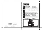
Figure 4: Junction Box Left:Front Side, Right: Back Side
The junction box is used to pass through the communication between the PC
and the RCPD. For this purpose it has a 25-pin D-sub-miniature socket, (16)
for the data cable (5) to the PC and a flanged socket (17) for the cable (7) to
the RADAR RCPD (3).
The power supply for the RCPD and Transceiver is also integrated in the junc-
tion box. An IEC connector for the mains supply of 230 VAC (17) is on the
front side of the case. On the back side are two sockets for banana plugs for
the connection of an alternative external DC power supply (19). The power
supply (24 VDC) for the RCPD and Transceiver is also passed through cable
(7).
Note : The junction box is not appropriate for outdoor operation.