ADDENDUM B page
8
3.
Observe position of the screen splitting line on the screen. If the line does not run through the
center of the marks or while zooming in and out the screen splitting line moves, perform steps
a-f.
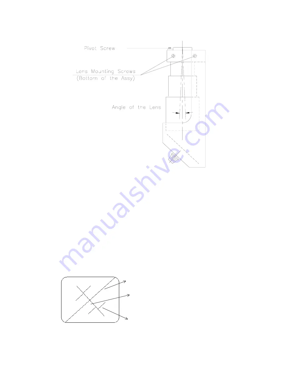
DWG # 8
a.
Loosen mounting block screws.
b.
Loosen pivot screw making 2 turns counterclockwise.
c.
Gently push the lens toward the unit until lens is in the extreme right hand position.
d.
Zoom out until image such as DWG # 9 is seen.
e.
Adjust positioning knobs (See DWG # 7) to move the screen splitting line symetrically
in the center of the 4 marks.
f.
Zoom in and out and observe if the screen splitting line moves between 4 marks. If the
screen splitting line does move, turn the pivot screw approximately 1/4 turn. Zoom in and
out to check if line moves. Continue turning screw 1/4 turn until the screen splitting line
remains stationary.
4.
Turn both positioning knobs (See DWG # 7) until the image of the pattern is positioned
approximately in the center of the screen and the line runs through the center of the pattern. (See
DWG # 9)
DWG # 9
5.
Observe the diagonal line. If it appears to be broken (See DWG # 10), follow the steps a-c.
SCREEN SPLITTING
LINE
MARK ON THE DIAGONAL
LINE
DIAGONAL LINE


