background image

ADDENDUM B     page

2

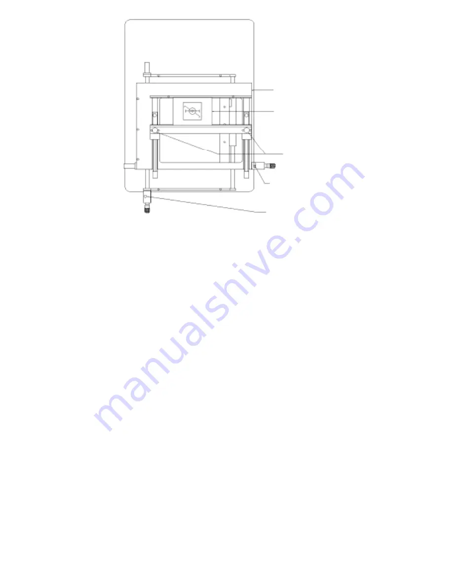
Top view of board holder.
Arm not shown for clarity.
FIG A                                  


To place Gun Sight Assembly into board holder as shown above in FIG. A, procede
as follows:

Loosen black knobs marked C to allow movement of the front PCB holding rail.


Move the front rail so that the Gun Sight Assembly can be held in place by the front and rear 
PCB holding rail.  Tighten the black knobs marked C to secure the Gun Sight Assembly in 
place.

To position the Gun Sight Pattern in the center of the vacuum cup do the following:

Move the two levers marked D and E so that when you grab the two black knobs marked C


the board holder moves freely. Position the Gun Sight Pattern in the center of the vacuum cup. 
Move the two levers marked D and E back into their original position to lock the board holder
in place.

6.

Adjust the illumination and the macro zoom lens to obtain a clear picture of the gun sight


pattern.


a.

The illumination is adjusted by rotating the lower red knob on the left side of the 
placement arm.  This adjusts the illumination for the object in the board holder.


 b. 

The focus on the zoom lens is adjusted by rotating the large ring located at the bottom of 
the lens.


 c.

The  Zoom is adjusted by rotating the middle ring.
The upper ring on the lens is used to adjust the aperture (i.e., how much light the camera
sees)

7. 

Place the second gun sight plate over the gun sight pattern on the assembly. Note: This gun sight 
pattern should be face down.

8. 

Set the vacuum selector switch to trigger from the vacuum pickup head.   Bring the vacuum


pickup head down and pick up the top gun sight plate off the gun sight alignment assembly.  
Move the pickup head to the uppermost position.  Place the height adjustment block on the nest 
holder and slide the block under the plate.  If the block does not go under the plate rotate the 
“Z” adjustment knob clockwise until the block just clears the plate.  If there is a gap between the 
plate and the height adjustment block rotate the “Z” adjustment knob counterclockwise until the 
block just clears the plate. Slide nest holder and height adjustment block back (away from the 
unit) and remove block. Remove height adjustment block.

9.

Move the beam splitter out from the arm assembly to its forward most position.  Adjust the
illumination until you see both the top gun sight plate marking and the bottom gun sight plate

Board Holder
RBH-D

Gun Sight
Alignment Ass’y
PN 20066

Rail Tension
Knobs

Locking Lever
X Movement

Locking Lever
Y movement

A

B

C

D

E

Summary of Contents for BGA-3590 Series

Page 1: ...BGA CSP Rework System BGA 3590 Series CSP 3500 Series USER GUIDE www metcal com Precision Systems for the Electronics Bench P N 7000 1251 Ver A 9 01 ...

Page 2: ...ii BGA 3500 Series Manual 5 01 ...

Page 3: ...eration 11 SECTION VI Additional System Features 18 SECTION VII Troubleshooting 18 SECTION VIII Spare Parts and Optional Accessories 21 SECTION IX Nozzle Selection Chart 23 SECTION X Warranty and Service 24 Addendum A BGA Windows Program manual A1 A12 Addendum A page 1 Addendum B Calibration Procedure B1 B11 Addendum B page 1 TABLE OF CONTENTS 2001 Delawre Capital Formation Inc All Rights Reserved...

Page 4: ...rce Temperature 752 F 400 C from BGA 3582 Micro Oven Temperature Control Range Closed loop K type thermocouple feedback Maximum PCB Dimensions 20 25 489mm x open frame PCB Thickness 0 031 0 125 0 8mm 3 2mm Component Maximum Weight 92 oz 0 055 kg Component Types BGA QFP PLCC TSOP SOIC CSP Airflow 3 20 l min Top Heater Element 28VAC 280W max Vacuum Pump 12 VDC 15 Hg 381mm Hg Base Unit Dimensions 22 ...

Page 5: ...split field vision system monitor 100V Japan only NTSC BGA 3591J SN BGA rework system with high power under board heater100v Japan only CSP 3501J G CSP Rework System 100V NTSC w o monitor BGA 3592 N G BGA Rework System 230V NTSC w o monitor CSP 3502 N G CSP Rework System 230V NTSC w o monitor Please note Monitor will be supplied locally and specification will vary Environmental Conditions all mode...

Page 6: ...luable resource It explains the system s options features specifications and outlines the correct operation of your BGA CSP 3500 Rework System If any problems should occur dur ing setup or operation of your system contact your local Metcal Representative or Metcal s Applications Engineering Department at 650 325 3291 or e mail to experts metcal com This Metcal BGA CSP 3500 Series Rework System pro...

Page 7: ... minutes II SYSTEM FEATURES AND ACCESSORIES BGA CSP 3500 REWORK SYSTEM INCLUDES BGA CSP 3500 Series Base Unit BGA CSP 3500 Control Unit with BGA 1 Microprocessor digital module High Resolution Camera 1 2 CCD with C mount Open ended adjustable size board holder with under board support 20 High Resolution Color Monitor Optional BGA 3528 Micro Oven Head Assembly ACCESSORIES INCLUDED WITH SYSTEM MX 50...

Page 8: ...oard support until they contact the bottom of the PCB and provide support This underboard support is constructed of a special material that reduces the absorption of heat however in some instances it may interfere with the transfer of heat energy from the underboard heater Please position it away from the component under rework 12 X Axis Lock Unlock Bar Set into the horizontal position to unlock t...

Page 9: ...7 BGA 3500 Series Manual 5 01 1 2 3 11 13 12 9 6 7 17 4 16 18 15 8 14 10 Figure 1 5 ...

Page 10: ...bs are used for adjusting the projected image so that it is centered in reference to the monitor 10 Tooling Plate Holder Component Slide The adjustable MPVB tooling plate is mounted here This is used to introduce the component into the optical path of the prism and ensure that component pick up is centralized in reference to the vacuum pipette 11 Vacuum Selector Switch When this switch is in the m...

Page 11: ...Place and Lift modes of machine operation 11 Top Display Up Down Keys Use these keys to increase or decrease any displayed value in the upper display during setting up of the profile i e temperature The keys also change system parameters i e C to F 12 Type K Thermocouple Input When the switch 18 is in the Thermocouple position the bottom display will read the temperature measured by the K Type the...

Page 12: ... environment 1 Remove the BGA CSP 3500 Main Unit Control Unit Camera 20 High Resolution Monitor optional and all accessories from there shipping containers 2 Mount the camera to the lens by rotating the camera clockwise so that it fully screws onto the top of the lens assembly 3 Connect the black cable extending from the rear of the BGA CSP 3500 base unit to the connector marked 12VDC IN located o...

Page 13: ...ol Unit Set the BGA CSP 3500 Main power switch Control Unit power switch and the Monitor power switch to the on position Your BGA CSP 3500 Series Rework System is now ready for operation V QUICK GUIDE TO CALIBRATION OF BGA CSP 3500 IS YOUR PICTURE CORRECT Note This should be done with a PCB in the board holder What to check Is the camera mounted so the video image is straight If not rotate the cam...

Page 14: ...propriate vacuum pipette onto the vacuum head of the placer 4 Pull the Board Holder Selection Knob towards you and slide the board holder so that it locks into posi tion underneath the Placer Note The following steps are to be followed after deposition of solder paste or flux has been completed 5 Adjust the board holder to accommodate the PCB by loosening the two black knobs and sliding the frame ...

Page 15: ...coarse adjustments at this point by sliding the board holder to allow the com ponent legs or balls and the corresponding land pattern to be roughly overlaid After this image is obtained lock the X and Y axis by switching the locking bars from the horizontal to the vertical posi tion After both the X and Y axis are locked fine adjustments can now be made by rotating the X and Y axis micrometers unt...

Page 16: ... head assembly in a similar fashion SMT nozzles are threaded and simply screw into the nozzle adapter 13 Position the Micro Oven Nozzle over the center of the component using the X and Y micrometers for fine adjustments 14 Press the start button or click on the start icon to begin the reflow cycle The system will cycle through the complete profile and automatically stop at the end 15 Raise the noz...

Page 17: ...ou have just removed will be suspended inside the nozzle by the vacuum tube 10 Using a heat resistant material position it under the nozzle and turn the vacuum off This will release the component from the BGA head assembly Please do not use your hand to catch the component even after the cooling cycle the component can be extremely hot SITE PREPARATION Solder Removal Prepare the site to receive a ...

Page 18: ...he prism to clear the placement path rotate the Z axis knob to place the stencil into contact with the board Deposit the solder paste using the squeegee supplied with the stencil Raise the stencil to the top alignment position pull out the prism and inspect the pasted board under the high magnification supplied by the BGA CSP 3500 placement unit Solder Paste Application using the BGA Stenciling Te...

Page 19: ...llows the BGA CSP 3500 to use Metcal s range of FCR MTR Nozzles for SMT applications as well as custom designed SMT nozzles to accommodate virtually any component When using the nozzle adapter the exhaust of the SMT nozzle is extended about 1 from the RTD measur ing device as compared to BGA Micro Oven Nozzles Because of this 1 extension exhaust temperature will decrease about 100 C from the sourc...

Page 20: ...e thermocouple switch on the BGA 1 module to the thermocouple position 3 At this point the bottom display will read the temperature of the external thermocouple in the scale F or C that you have previously selected NOTE The BGA 1 module will display the temperature of the external thermocouple whenever the time thermocouple switch is in the thermocouple position If this switch is in the thermocoup...

Page 21: ...position 4 Problem Both images are overlaid perfectly on the monitor but when the component is placed it is misaligned Probable Cause Machine is out of calibration Possible Solution Calibrate the machine The calibration procedure is thoroughly discussed later in the manual Z Axis height is not correctly set Possible Solution The component height knob needs to be adjusted so that the component lead...

Page 22: ...arly visible 8 Problem You are unable to slide the prism in and out of the placement arm assembly Probable Solution The locking arm for the Z axis control knob is on the wrong side of the prism slider pin Remove the side cover and move the locking lever into the correct position MICRO OVEN 1 Problem When running the BGA S1 Software there is an error stating that communication cannot be established...

Page 23: ...uum seal Do not exert exces sive pressure or the component may not lift Select the appropriate size vacuum cup for your application and insert onto the vacuum rod 4 Problem Operator cannot remember security code and is locked out of the BGA System Solution Contact your local Metcal representative or Metcal Applications Engineering for instructions on overriding and entering a new security code 5 P...

Page 24: ...CSP 3500 Systems AC 525 PH SET Heater pair 500W 230V BGA 3000 CSP 3500 Systems 70399330 Heater pair 200 W 100V BGA 3000 CSP 3500 Systems AC 725 PH SET Heater pair 750W 115V BGA 3500 Systems AC 725 PH SET Heater Pair 750W 230V BGA 3500 Systems 70399330 Heater Pair 700W 100V BGA 3500 Systems 20835 Fan Detector and Fan Motor Driver PCB 20731 Temperature Controller PCB 100V 115V Systems 20734 Temperat...

Page 25: ...6 276 27 6mm x 27 6mm BGA 315 315 31 5mm x 31 5mm BGA 380 380 38mm x 38mm BGA 403 403 40 3mm x 40 3mm BGA 450 450 45mm x 45mm BGA 490 490 49mm x 49mm BGA NA Nozzle Adapter for FCR Nozzles CSP NOZZLES PART NUMBER INTERNAL DIMENSIONS CSP 060 060 6mm x 6mm CSP 077 095 7 7mm x 9 5mm CSP 080 080 8mm x 8mm CSP 080 095 8mm x 9 5mm CSP 085 099 8 5mm x 9 9mm CSP 085 102 8 5mm x 10 2mm CSP 091 132 9 1mm x 1...

Page 26: ...ished with Metcal s BGA Stenciling Templates Theses templates allow the precise application of solder paste without worrying about contact with surrounding parts on the PCB Since the component is pasted instead of the board operators find this to be a much faster and simpler solution Please contact your local Metcal representative for information and availability Custom sizes and styles are availa...

Page 27: ...ct Set Com Port and choose a com port connected to BGA unit Select File choose Exit to quit and restart the program Enter password Enter the same security number set in BGA unit only if this security number was set and click OK Select a profile Click on Place or Lift icon on the top left corner of control panel shown on screen to choose a place or lift profile Click on or to increment or decrement...

Page 28: ...he appropriate temperature of the top air should be set in order to ensure solder joints reach their melting point Note For the removal mode the pick up solenoid will be triggered at the end of this cycle allowing the component to be automatically removed from the PCB Cool zone is used to cool down the chamber of the micro oven and the solder connections in the place mode allowing the solder to so...

Page 29: ...d on the disk Select File from menu and choose New Profile and enter new data Select File from menu and choose Save File and assign a file name for the new profile on the file dialog window Click here to accept the selection Click here to abort the selection Click here to enable the computer to search for an empty profile for you Click here to pop up the list of profiles and then select a profile ...

Page 30: ...cuum when activated by software and RS 232 is disconnected will not revert to manual control unless the program is closed down by quitting application or the power is turned on and off again on the BGA 3000 unit Click here to increment or decrement the profile number Click here to choose the place or lift profile Click here to Start the cycle Note Icon change can be match or space shuttle See Opti...

Page 31: ...emperature of a given probe at a specific time The T C probe is typically placed in between the chip and the PCB by the first balls when trying to establish a removal process for BGA for the first time It can be placed in any other desired location The vertical dotted lines are designed to help read the temperature curves easily The temperature and time measurement window is displayed at the botto...

Page 32: ...ut Curve and highlight the name of the curve to be deleted This curve can be pasted on any graphics windows by selecting Paste Curve from the menu For a short cut select a curve to be deleted by moving the mouse pointer to the top of this curve Click on the left button of the mouse and choose Cut Curve on the pop up menu To change attributes of the curve Highlight a graphics window and select View...

Page 33: ... graph to the desired time setting and release the left button Note A time measurement bar cannot be added to a graphics window which does not have actual temperature curves Delete time measurement bars Highlight a graphics window select View on the menu bar and select Time Measurement Bars Choose Delete Time Bar and choose the time setting mm ss of the bar to be deleted How to add delete Time Mea...

Page 34: ...d the left button of the mouse Move the mouse to the target window and release the left button The copy is complete Another way to copy profile settings is to move the mouse pointer to the free space on the window Click on the right button of the mouse to open the edit menu Note The right button of the mouse may be used by other applications and a different menu would appear How to get the editing...

Page 35: ...rocess Lock BGA system Select Security on from menu and choose Lock BGA System Enter password on the pop up window You will be asked to enter the new password twice if no password has been set and click OK The BGA system is unlocked if the BGA system was in the lock mode previously Otherwise a dialog window appears and will ask you to select a security level Click OK to select security level 2 whi...

Page 36: ...e disk Update or restore the settings of BGA module Place current settings of the profile on the copy buffer Place the selected curve to the curve buffer Delete the selected curve and place copy to the curve buffer Paste the curve on the curve buffer to the current graphics window Start control panel setting process Paste the Bit Map Image of the current window to the Clipboard Stop the current pr...

Page 37: ...or Fahrenheit Select a display mode for the timer at the right corner of the Tool Box Add Delete the time measurement bars Change the attributes of the selected curve Open the graphics window of the current profile window Select and highlight a window from the list of windows opened The mark indicates the particular item is enabled The selected default temperature scale is used when a new profile ...

Page 38: ...d select File from menu and choose Print Window Image The Tool Box Show the version of this program and the BGA module here Select the installation drive Select here to create the BGA manual file in Microsoft Word format from the optional manual disk Note Microsoft Word is trademark of Microsoft Corporation Start Stop Lock Recall Update Actual Process Cycle Cycle Editing Settings Settings Temperat...

Page 39: ...UP 1 The camera has been pre set at the factory to the following a C mount adapter has been locked with C mount fixing screws to 1 1 2 turns from fully home b Shutter speed has been set NTSC PAL c White balance set to auto Note Please do not change these settings SYSTEM SETUP 1 Assemble the unit as described in the user s manual 2 Turn power on to the unit refer to users manual if necessary 3 With...

Page 40: ... located at the bottom of the lens c The Zoom is adjusted by rotating the middle ring The upper ring on the lens is used to adjust the aperture i e how much light the camera sees 7 Place the second gun sight plate over the gun sight pattern on the assembly Note This gun sight pattern should be face down 8 Set the vacuum selector switch to trigger from the vacuum pickup head Bring the vacuum pickup...

Page 41: ... right you must perform the factory calibration Refer to Section B step 13 to perform beam splitter adjustment NOTE Do not go to Step 11 if your unit is out of calibration Perform adjustment before proceeding to step 11 11 Using split vision knob rotate knob clockwise Split the image bringing the outer lines in toward the center of the screen Zoom in on the image and center on the screen if necess...

Page 42: ...n the right of the arm move the beam splitter out from the arm by moving the lever forward 4 Place a PCB Blank such OK PN 19703 into the board holder and position the largest component under the beam splitter 5 Adjust the illumination and the macro zoom lens to obtain a clear picture of the components full pattern a The illumination is adjusted by rotating the lower red knob on the left side of th...

Page 43: ...nes of the component on the PCB blank are lined up and continuous not broken E Turn screw E clockwise until the horizontal lines of the component on the PCB blank are lined up and continuous not broken If you cannot line up the horizontal lines turn the split adjustment knob and additional 10 15 F Turn split vision knob clockwise 45 and back counterclockwise until the outline lines up again in bot...

Page 44: ...sing the zoom lens magnify the circle on the fixed pattern plate until the circle fills the video screen Using the two positioning knobs on the vision assembly move the circle plate to the center of the screen See DWG 7 9 Retreat the beam splitter and install the removable pattern plate face down onto the dowel pin 10 Move the vacuum head to the low position until the vacuum head touches the patte...

Page 45: ...r marks on the diagonal line are visible on the screen two on each side of the division line See DWG 9 2 Magnify the image ring in the middle of the lens should be in the extreme counter clockwise position adjust sharpness largest ring on lens and illumination to obtain a clear picture If you do not see the 4 marks move the positioning knobs until the 4 marks appear on the screen ...

Page 46: ...reen splitting line symetrically in the center of the 4 marks f Zoom in and out and observe if the screen splitting line moves between 4 marks If the screen splitting line does move turn the pivot screw approximately 1 4 turn Zoom in and out to check if line moves Continue turning screw 1 4 turn until the screen splitting line remains stationary 4 Turn both positioning knobs See DWG 7 until the im...

Page 47: ...ligns itself c Tighten the top mounting screw DWG 11 D MAGNIFICATION ADJUSTMENT Images of the two patterns from the top and bottom plates should be magnified to the same size distances L1 and L2 If the image on the screen appears as shown in DWG 12B adjustment of the magnification is required DWG 12A DWG 12B SCREEN SPLITTING LINE BROKEN DIAGONAL LINE ...

Page 48: ...omponent from the adjustable V block Remove component nest from nest holder 3 Using your height adjustment block as a reference place the height adjustment on the nest holder and carefully attempt to slide under component Use the Z adjustment knob to adjust the height of the component so that the component leads just clear the adjusting screw on the block 4 Remove the height adjustment block 5 Rou...

Page 49: ...ADDENDUM B page 11 DWG 14 Do not touch this screw until after you adjust the block height in step D4 ...

Page 50: ...3440 2010 China No 22 Chao Yang Men Wai Avenue Beijing Prime Tower Room 1901 Chao Yang District Beijing P R China 100020 Tel 86 10 6588 3360 Fax 86 10 6588 3359 Metcal Headquarters 1530 O Brien Drive Menlo Park CA 94025 USA Tel 1 650 325 3291 Fax 1 650 325 5932 United Kingdom European Headquarters Eagle Close Chandlers Ford Eastleigh Hants S053 4NF England Tel 44 0 2380 489100 Fax 44 0 2380 489109...

Page 51: ...ELT V AC 525 PH SET 20719 20102 20002 19993 19984 19749 19732 19501 19510 17448 45878 41312 21207 21137 20734 20781 20835 20837 20907 21077 BGA 450 450 CSP 180 180 BGA 490 490 BGA 403 403 BGA 380 380 BGA 315 315 BGA 276 276 CSP 130 130 CSP 120 120 CSP 110 110 CSP 100 100 CSP 097 144 CSP 077 095 CSP 060 060 BGA 252 291 BGA 194 194 AC CLAMPSET 21149 CSP 150 150 ...

Reviews: