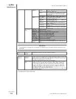
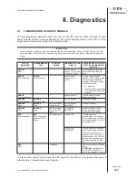


9-4
Operating and Maintenance Manual
Maintenance
code 504275001 Rev. September 2010
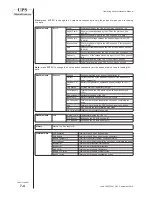
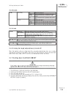
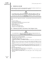
9.5 PREPARING THE UPS FOR MAINTENANCE IN THE MANUAL
MAINTENANCE BYPASS MODE.
If the Hot-Swap replacement procedure of the power modules is not applicable (paragraph
9.4), the modules can still be replaced by putting the UPS in maintenance bypass. This mode
is also necessary if ever it is requested to service or replace parts such as the control boards,
backplane, etc.
Attention: when working in the forced bypass and maintenance mode the load is not
protected
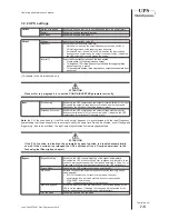
9.5.1 Manual bypass mode.
To put the UPS in the maintenance bypass mode proceed as follows.
1. Open the door of the ARCHIMOD
®
UPS;
2. Follow the guided procedure for “entering maintenance”.
To do this, navigate inside the Tools -> Bypass -> Entering maint. menu and follow the instruc-
tions displayed.
3. If you wish to continue with UPS maintenance press the ENTER button. After having pressed
ENTER the load is powered by the unit’s forced bypass. When the equipment is in the forced
bypass mode, the backlit status indicator on the front panel starts blinking quickly and is coloured
orange. Likewise, the LEDs on the various power modules also blink quickly.
4. Close the maintenance bypass disconnector switch.
5. Open the output disconnector switch.
6. Turn the UPS off keeping the ON/OFF button pressed for more than 2 seconds.
7. Open the mains input disconnector switch;
8. Open all the battery disconnectors of the UPS and of the ARCHIMOD
®
BATTERY units (if
installed);
ATTENTION: there are dangerous live parts inside the equipment due to the internal batteries
even if all the battery fuse holder disconnectors are opened. To remove the battery induced
voltage, remove at least 1 battery box from each battery shelf ( which will interrupt the battery
string series).
9.5.2 Replacing a power module or adding new modules
1. Make sure that the maintenance bypass procedure described in the previous paragraphs
has been scrupulously applied.
2. Extract the module after having loosened the two securing screws.
WARNING
There are two holes on the cover of the power module through which it is possible to see
two LEDs; if they are on it means there is dangerous voltage on the rear connector.
MAKE ABSOLUTELY CERTAIN THAT THESE LEDs ARE OFF before handling the module. If
they are on wait until they have turned off.
3. Check that on the new power module the two LEDs that can be seen through the two holes
on the cover are off. If they are on wait until they have turned off.
4. Put the new power module in place of the old one or in one of the available compartments if
you wish to increase UPS power.
5. Secure the power module to the unit’s frame with the 2 screws supplied, without tightening
too much; use only M4x20mm Allen screws;
Summary of Contents for ARCHIMOD 100
Page 2: ......
Page 69: ...12 1 Operating and Maintenance Manual Notes code 5040275001 Rev September 2010 12 Notes...
Page 70: ......
Page 71: ......