


counts (A/D Counts), to form a usable engineering value. The A/D counts range is 0 –
1,000,000 for 0-20 mA or 0-10 V depending on the strapping on the PCIO board. The
engineering value is calculated using the following formula.
(
)
MinValue
MaxValue
HiCnts
LoCnts
DCounts
/
A
Value
+
⋅
−
=
There is one set of parameters for the Setpoint and one for the Panel Meter.
Analog Input defaults and limits
Parameter Default
Min
Max
SP Lo Cnts
200,000
1
1,040,000
SP Hi Cnts
1,000,000
1
1,040,000
SP Min Value
0
-Design Feedrate
Design Feedrate
SP Max Value
Design Feedrate
0.01
150% of Design
Feedrate
PMtr Lo Cnts
200,000
1
1,040,000
PMtr Hi Cnts
1,000,000
1
1,040,000
PMtr Min Value
0
-100.0
100.0
PMtr Max Value
100.0
0.01
1000000.0
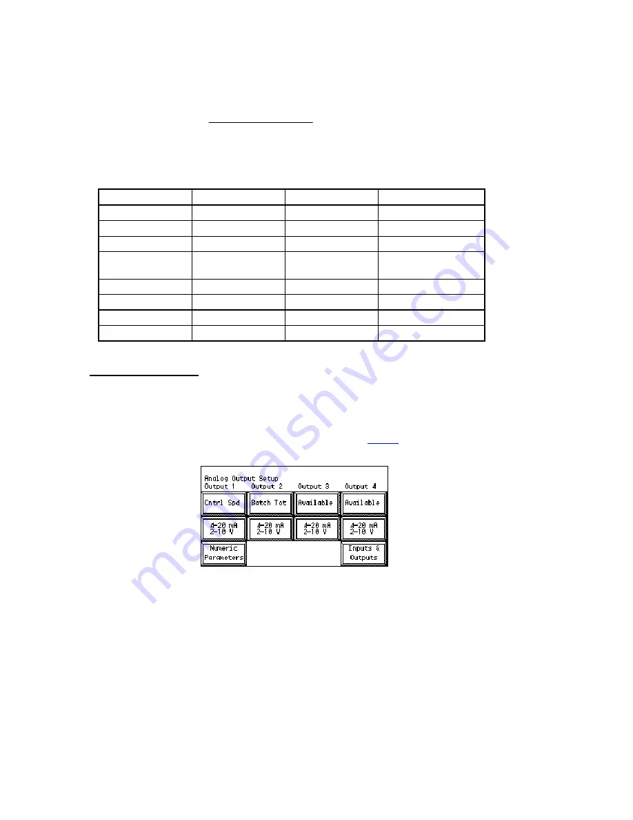
Analog Outputs Setup
There are two analog outputs available per installed PCIO board, so you can have up to
four analog outputs. In the Analog Outputs menu, you select what you will be using the
analog outputs for. You also select between 0-20 mA (0-10 V) and 4-20mA (2 – 10 V)
type outputs.
Refer to the MC³ hardware reference manual, available at
inputs.
Analog Output Setup
By pushing the button under a specific Output, you can select what it will be used for The
button caption will change between:
Cntrl Spd
Speed Demand signal, for feeding device drive.
Feedrate
Actual material flow, with the full scale output at Design Feedrate.
Weight
Net Weight in the hopper, with the full scale output at Design Weight.
Setpoint
Actual, used Setpoint, with the full scale output at Max Batch Wt.
Batch Tot
Actual, batch total, with the full scale output at Max Batch Wt.
Available
This mode is used in rare occasions when the output is directly
controlled by Serial Communications. The typical application would
be a PLC taking over an unused output for other purposes than
feeder control.
35.00.EX O&M Manual
32
Summary of Contents for MC3 35.00.EX
Page 5: ......