


Copyright Meritor, Inc., 2021
MM-96147 / Revised 03-21
Page 97
(16579)
Printed in USA
18 Appendix
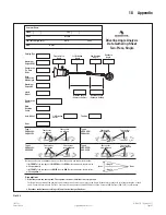
Driveline Angle Analysis
Data Gathering Sheet
Two-Piece, Single
Transmission
Top Gear
Ratio
Phasing Type
Maximum
Engine RPM
Maximum
Engine HP
Rear
Suspension
Ride Height
Main
Driveline
Series
Transmission
Model
I/A Driveline
Series
Axle Model
Customer Name:
Phone:
Fax:
OEM:
Model:
VIN: (Last 6 digits only)
Year:
Unit:
Date:
DSM:
Transmission
Angle
1st Driveline
Angle
2nd Driveline
Angle
Rear Axle
Angle
Driveline Length
(Center to Center)
Driveline Length
(Center to Center)
Ratio
Tire Size
Clutch
Model
( )
( )
Assumptions
1. Drivelines are in the same plane. The top view shows all drivelines in a straight line.
For drivelines outside of the same plane, measure the offsets of each joint to the frame. Measure joint center to joint center lengths of each
shaft. Fax this information to OnTrac’s Customer Service Center at 248-435-5580 or call the Center at 866-OnTrac1 (668-7221) for assistance.
2. Drivelines are balanced according to Meritor’s driveline specifications.
Type 1
PARALLEL –
PARALLEL
Type 2
CROSSED –
PARALLEL
Type 3
PARALLEL –
CROSSED
Type 4
CROSSED –
CROSSED
Front
Rear
Before you measure a component, go to the side of the vehicle and look at the driveline:
If the
FRONT
of the component is
HIGHER
than the
REAR
of the component, the dimension
will be
positive (+)
.
If the
FRONT
of the component is
LOWER
than the
REAR
of the component, the dimension
will be
negative (–)
.
These yokes
are aligned
These yokes
are aligned
These yokes
are misaligned
These yokes
are aligned
These yokes
are aligned
These yokes
are misaligned
These yokes
are misaligned
These yokes
are misaligned
Angle
Angle
Fig. 18.2