


Copyright Meritor, Inc., 2021
MM-96147 / Revised 03-21
Page 39
(16579)
Printed in USA
5 RPL Series Permalube
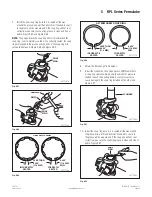
7. Install the new snap ring. Ensure it is seated all the way
around the groove. Use a drift and hammer if needed to seat it
in the groove all the way around. If the snap ring will not seat
correctly, make sure the snap ring groove is clean and free of
debris. Figure 5.87 and Figure 5.88.
NOTE:
The gap between the snap ring ends is smaller when the
snap ring is not completely seated. Once correctly seated, the snap
ring will expand in the groove and the ends of the snap ring will
spread further apart. Figure 5.89 and Figure 5.90.
4011761a
SNAP
RING
Fig. 5.87
4011762a
SNAP
RING
DRIFT
HAMMER
Fig. 5.88
4011773a
INCORRECTLY
SEATED
CORRECTLY
OEM SNAP RING
SEATED
0.450"
(11.4 MM)
MIN.
LESS THAN
0.450"
(11.4 MM)
Fig. 5.89
4011773b
INCORRECTLY
SEATED
CORRECTLY
SEATED
0.450"
(11.4 MM)
MIN.
LESS THAN
0.450"
(11.4 MM)
AFTERMARKET SNAP RING
Fig. 5.90
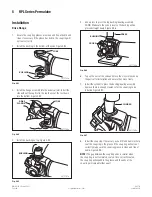
8. Rotate the drive fl ange 180 degrees.
9. Install the cylinder on the end and press DOWN until there
is snap ring clearance. Apply only the amount of pressure
needed to push the bearing down. Excess pressure may
cause damage to the snap ring installed on the other end.
Figure 5.91.
4011760a
CYLINDER
Fig. 5.91
10. Install the snap ring. Ensure it is seated all the way around
the groove. Use a drift and hammer if needed to seat it in
the groove all the way around. If the snap ring will not seat
correctly, make sure the snap ring groove is clean and free of
debris. Figure 5.92.
4011764a
SNAP
RING
Fig. 5.92