


Copyright Meritor, Inc., 2021
MM-96147 / Revised 03-21
Page 86
(16579)
Printed in USA
14 Measuring and Recording Driveline Angles
Measure Driveline Angles
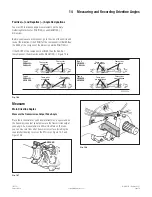
Measure the plan view angles by using either Method 1 or
Method 2.
Method 1
1. Measure and record the side view angles. Refer to the
procedure in this section.
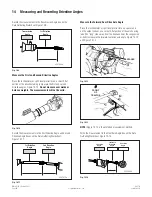
2. Measure the length of the driveline from the center of the
transmission universal joint to the center of the carrier
universal joint. Figure 14.27.
4005549a
Fig. 14.27
3. Measure the distance from the center of the transmission
universal joint to the frame rail. Use a carpenter’s square or
other straightedge if needed. Figure 14.28.
4005550a
Fig. 14.28
4. Measure the distance from the center of the carrier universal
joint to the frame rail. Use a carpenter’s square or other
straightedge if needed. Figure 14.28.
5. The universal joint plan view angle can now be calculated by
using Formula 1.
Method 2
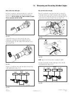
1. Measure the length of the driveline from the center of the
transmission universal joint to the center of the carrier
universal joint. Figure 14.27.
2. Attach a plumb bob to the frame rail in line with the
transmission universal joint. Mark a point on the ground just
below the plumb bob. Figure 14.29.
4005551a
Fig. 14.29
3. Repeat Step 2 for points in line with the carrier universal joint
and a spot in between the universal joints.
4. Draw a straight line connecting the points on the ground.
Figure 14.30.
4005552a
Fig. 14.30
5. Attach a plumb bob to the center of the transmission universal
joint. Mark a point on the ground just below the plumb bob.
Figure 14.31.
4005553a
Fig. 14.31