


56
FUNCTION
and then the
PgDn
soft key. To retreat to the prior page, press
FUNCTION
and then
PgUp
.
Once engaged, the
PgUp
and
PgDn
soft keys remain active until the
Up
or
Down
soft keys or
FUNCTION
is pressed again.
List / Edit Configs:
Lists all stored HART configurations by Tag Number. Once a
desired tag is located with the cursor, pressing the
Select
soft key
displays header information to help the user confirm the identity
and origin of the configuration. Pressing
Select
again opens the
configuration for review and editing as needed. Any configuration
in the list can be sent to another HART device of the same
manufacture and model number. This feature enables fast
commissioning of replacement devices, cloning of existing
systems, or re-configuring for changes in process conditions or
batch runs. New entries to this list are loaded to the bottom of the
list. If multiple entries for one device are shown, the most recently
saved configuration is always listed last.
Entries in this list may have been saved directly from a connected HART device, created in the MFT using
the
Create Configs
function, copied from another configuration and renamed, or created by editing an
existing file. MFT will also list configurations downloaded from the separately available Meriam Device
Management System software (see www.meriam.com for more information).
Create Configs:
The
Create Configs
function allows the user to configure a HART device file in Offline Mode for sending to
the intended device later when connected in the Online Mode. Use the soft key controls to move through
the list and select the device model number required. The menus prompt the user to make the necessary
configuration selections, tag the file for later retrieval and use, and edit configuration lines as required. This
function can be locked out. See the Lockout Section of this manual for more information.
Delete Individual Configs / Clearing Configuration Memory:
Individual stored Configurations may be deleted with MFT
Del
soft
key functions (see example at right). A delete confirmation screen is
provided to prevent unintended deletions. The
Del
key only hides the
record from the MFT screen; it does not clear memory space.
To clear
all
configurations from memory (including active and hidden
configs), enter the
HART Offline Menu Screen
and select the
Delete All Configs
option. The MFT will ask “Delete ALL Configs…
ARE YOU SURE???” Select
Yes
to clear
all
stored configurations
from memory.
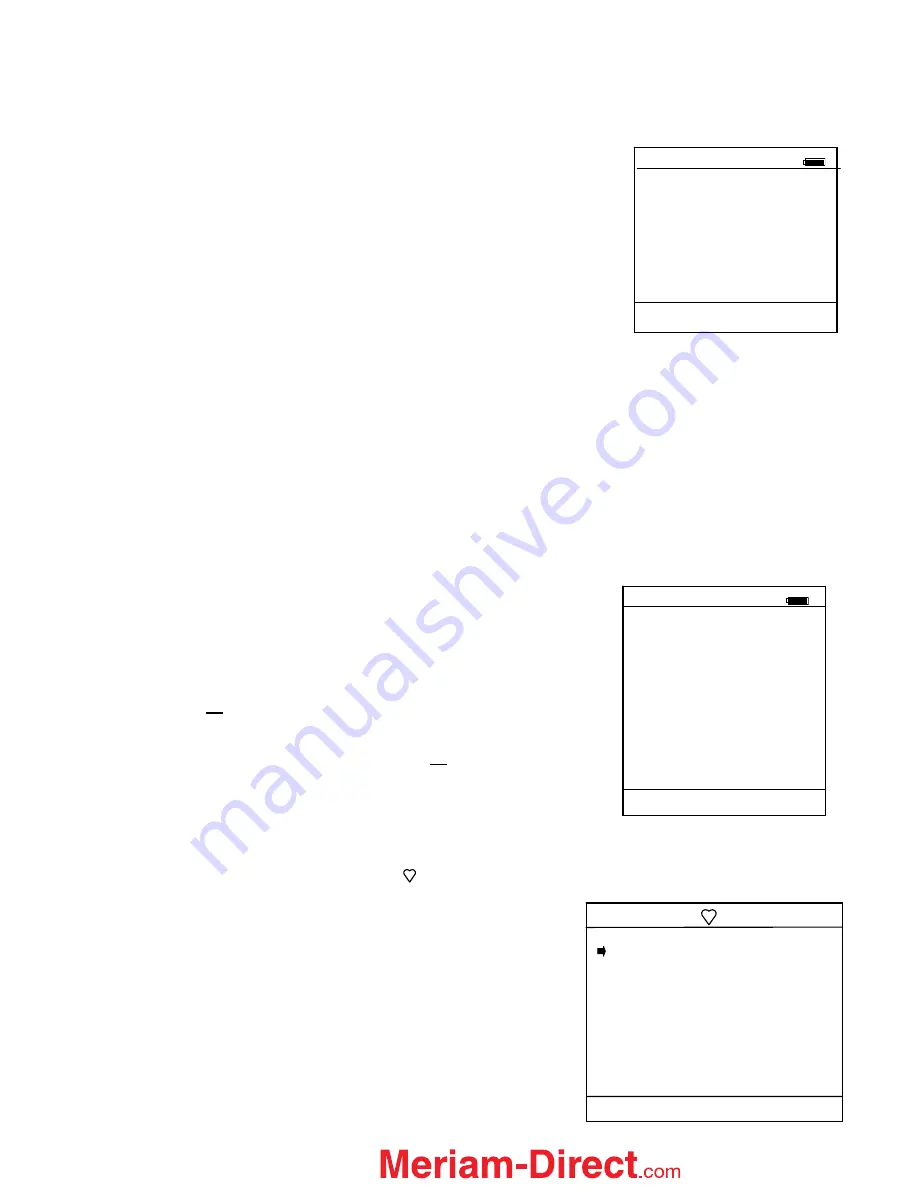
HART ONLINE MODE
Once a HART device is located, the MFT enters the
Hart Device Online Screen
as shown below. The word
“Hart” appears in the top left of LCD. The symbol will “flash” when HART communications have been
established.
Note: The screen at right illustrates a Rosemount 1151 rev.
5 HART display. Screen configuration may vary depending
on the HART device connected. For more information,
please refer to the owner’s manual for the HART device
under test.
Hart
1151: Pump 8
Device Config
Pres: 0.000 InH20
AO:
4.000 mA
LRV:
0.000 InH20
URV: 104.8 InH20
% of Range: 0.000%
AO Fixed
Up Down Select Back
Offline List / Edit
Configs Screen
Offline
List/Edit Configs
PT-105B
DPT-201C
TT-312 A
TT-312 A
FE-201
FE-201
PT-6174
Up Down Select Back
Delete Individual Configuration
Offline
List/Edit Configs
PT-105A
Device ID 6121486
Single Var
E Hauser
Cerabar S
Complete Config
Uses DOF 11070702
81 Variables
02/21/03 4:50 PM
Copy
Del
Select Back
1.888.475.5235