


Powerhead
90-8M0050731 MAY 2011
Page 4A-45
8. If necessary, clean the connecting rod bearing surfaces, as follows:
a. Ensure that etched marks on the connecting rod (crankshaft end) are perfectly aligned with etched marks on the
connecting rod cap. Tighten the connecting rod cap attaching bolts securely.
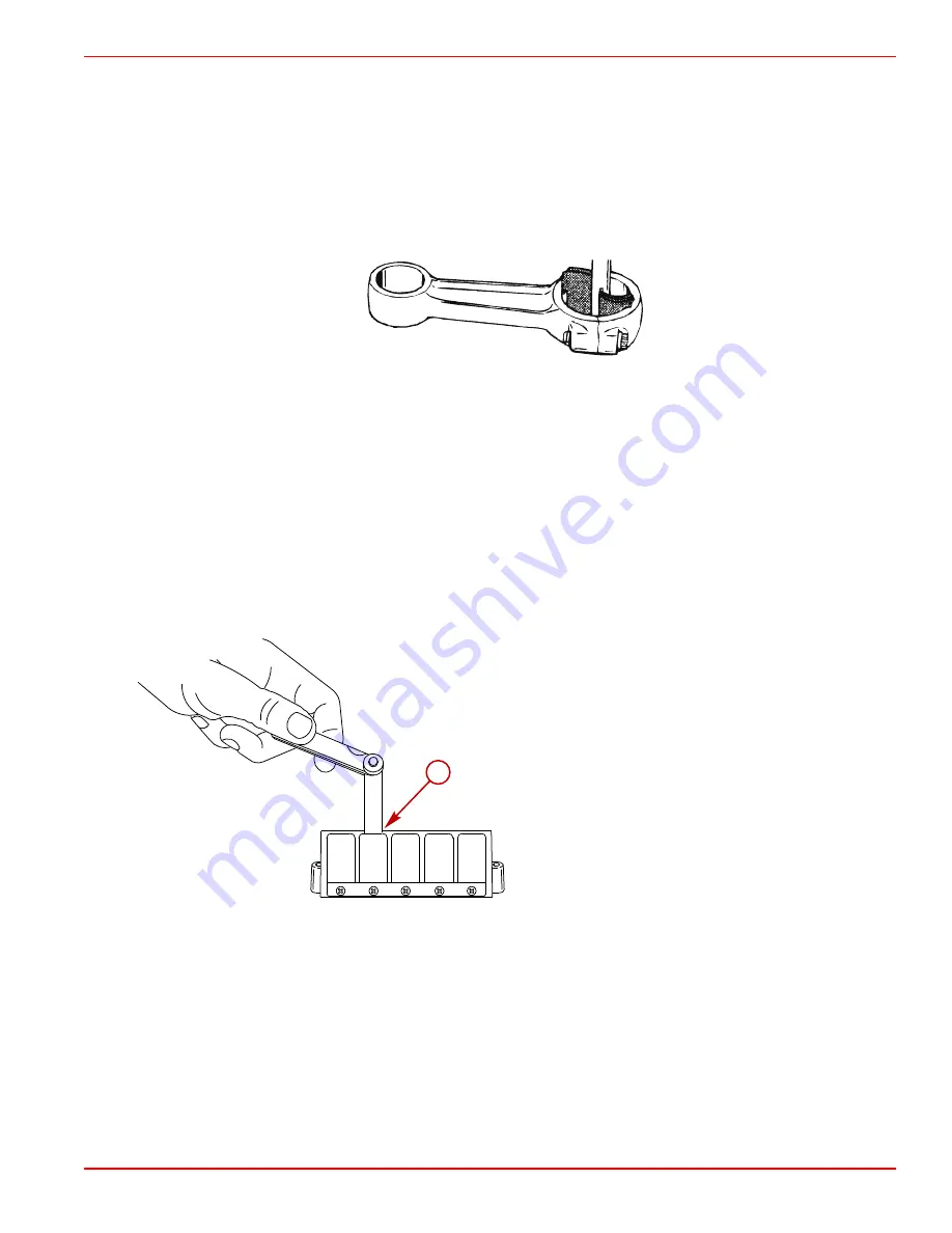
b. Clean the crankshaft end of the connecting rod by using crocus cloth placed in a slotted, 9.5 mm (3/8 in.) diameter shaft,
as shown. Secure the shaft in a drill press and operate the press at high speed, keeping the connecting rod at a 90°
angle to the slotted shaft.
IMPORTANT: Use only crocus cloth to clean the bearing surface at the crankshaft end of the connecting rod. Do not
use other types of abrasive materials to clean the bearing surface.
c. Clean the connecting rod just enough to clean up the bearing surfaces. Do not continue to clean after marks are removed
from the bearing surfaces.
8695
d. Using a 320 grit carborundum cloth (instead of crocus cloth), clean the wrist pin end of the connecting rod using the
same method as in step "b."
e. Thoroughly wash the connecting rods to remove abrasive grit. Recheck the bearing surfaces. Replace any connecting
rod that cannot be properly cleaned up. Lubricate the bearing surfaces of the connecting rods being reused with light
oil to prevent rust.
Reed Block Assembly
IMPORTANT: Do not remove the reeds from reed blocks unless replacement is necessary. Do not turn used reeds over for reuse.
Replace reeds in sets.
1. Thoroughly clean the gasket surfaces of the reed blocks and reed block housing. Check for deep grooves, cracks, or distortion
that could cause leakage. Replace parts as necessary.
2. Inspect the reed block neoprene surface for wear, cuts, or abrasions. Replace the reed blocks as necessary.
3. Check for chipped and broken reeds.
a -
0.51 mm (0.020 in.) opening
NOTE: Allowable reed opening is 0.51 mm (0.020 in.) or less. Replace reeds if either reed is standing open more than 0.51 mm
(0.20 in.).
End Bearing Bleed System
1. Check the rubber bleed hoses. Replace any cracked, cut, or deteriorating hoses.
2. Check operation of the lower end cap check valve. If the valve is working properly, air can be drawn through the check valve
one way only. If air can pass through a check valve both ways, replace the valve.
a
8687
Summary of Contents for 200 OptiMax Jet Drive
Page 5: ...Page iv ...
Page 30: ...General Information Notes 90 8M0050731 MAY 2011 Page 1C 5 ...
Page 43: ...General Information Notes Page 1C 18 90 8M0050731 MAY 2011 ...
Page 84: ...Ignition Notes 90 8M0050731 MAY 2011 Page 2A 3 ...
Page 89: ...Ignition Page 2A 8 90 8M0050731 MAY 2011 Electrical Plate Engine Harness 44731 1 2 3 4 5 6 ...
Page 147: ...Charging and Starting System Notes Page 2B 36 90 8M0050731 MAY 2011 ...
Page 153: ...Timing Synchronizing and Adjusting Notes Page 2C 6 90 8M0050731 MAY 2011 ...
Page 156: ...Fuel Pump Notes 90 8M0050731 MAY 2011 Page 3A 3 ...
Page 245: ...Direct Fuel Injection Notes Page 3B 82 90 8M0050731 MAY 2011 ...
Page 248: ...Oil Injection Notes 90 8M0050731 MAY 2011 Page 3C 3 ...
Page 261: ...Oil Injection Notes Page 3C 16 90 8M0050731 MAY 2011 ...
Page 277: ...Powerhead Page 4A 12 90 8M0050731 MAY 2011 Cylinder Head 14 44903 1 2 3 3 4 5 6 7 8 9 10 ...
Page 326: ...Powerhead 90 8M0050731 MAY 2011 Page 4A 61 Starboard Side Oil Hose Routing 45579 ...
Page 327: ...Powerhead Page 4A 62 90 8M0050731 MAY 2011 Port Side Oil Hose Routing 45580 ...
Page 339: ...Powerhead Notes Page 4A 74 90 8M0050731 MAY 2011 ...
Page 346: ...Cooling Notes 90 8M0050731 MAY 2011 Page 4B 7 ...
Page 349: ...Cooling Notes Page 4B 10 90 8M0050731 MAY 2011 ...