


Powerhead
90-8M0050731 MAY 2011
Page 4A-39
Universal Puller Plate
91‑37241
Powerhead Stand
91‑ 30591T 1
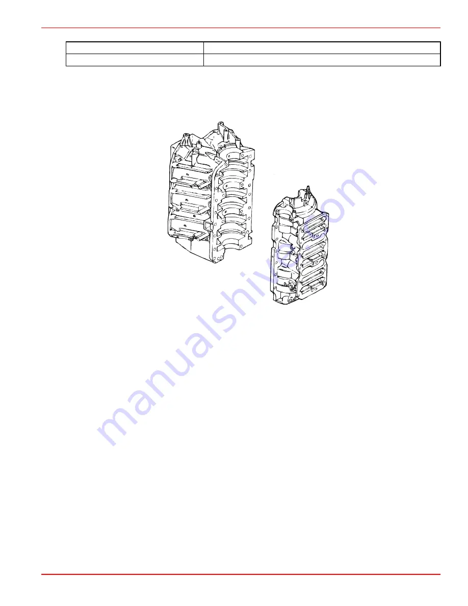
Cleaning and Inspection
Cylinder Block and Crankcase Cover
IMPORTANT: The crankcase cover and cylinder block are a matched, line‑bored assembly and must never mate with a different
crankcase cover or cylinder block.
8650
IMPORTANT: To prevent damage to components, remove all hoses, check valves, and other oil system components before
submerging the cylinder block in cleaning solution.
1. Thoroughly clean the cylinder block and crankcase cover. Ensure that all sealant and old gaskets are removed from matching
surfaces. Ensure that carbon deposits are removed from exhaust ports.
2. Inspect the cylinder block and crankcase cover for cracks or fractures.
3. Check the gasket surfaces for nicks, deep grooves, cracks, or distortion that could cause compression leakage.
4. Check all water and oil passages in the cylinder block and crankcase cover to ensure that they are not obstructed and that
the plugs are in place and tight.
Special Service Information
Grooves in the Cylinder Block Caused by Crankshaft Sealing Rings
Grooves in the cylinder block caused by crankshaft sealing rings are not a problem, unless installing a new crankshaft, and the
new sealing rings do not line up with the existing grooves in the cylinder block. If installing a new crankshaft, refer to
Crankshaft
Installation
to determine if the powerhead can be used.
Cylinder Bores
Inspect cylinder bores for scoring, scuffing, or aluminum transfer. Minor scoring or scuffing can be removed by honing. If aluminum
transfer has occurred, muriatic acid can be applied where the transfer of aluminum has occurred. Flush the cylinder bore with
water to remove any remaining acid.
Honing Procedure
1. Follow the hone manufacturer's recommendations for use of the hone and lubrication during the honing process.
2. A continuous flow of honing oil should be pumped into the work area.
IMPORTANT: Incorrect or excessive honing may damage the cylinder bores, leading to engine failure. Follow the hone
manufacturer's instructions. Measure the cylinder diameter often.
3. Start stroking at the smallest diameter. Maintain firm stone pressure against the cylinder wall to assure fast stock removal
and accurate results.
Summary of Contents for 200 OptiMax Jet Drive
Page 5: ...Page iv ...
Page 30: ...General Information Notes 90 8M0050731 MAY 2011 Page 1C 5 ...
Page 43: ...General Information Notes Page 1C 18 90 8M0050731 MAY 2011 ...
Page 84: ...Ignition Notes 90 8M0050731 MAY 2011 Page 2A 3 ...
Page 89: ...Ignition Page 2A 8 90 8M0050731 MAY 2011 Electrical Plate Engine Harness 44731 1 2 3 4 5 6 ...
Page 147: ...Charging and Starting System Notes Page 2B 36 90 8M0050731 MAY 2011 ...
Page 153: ...Timing Synchronizing and Adjusting Notes Page 2C 6 90 8M0050731 MAY 2011 ...
Page 156: ...Fuel Pump Notes 90 8M0050731 MAY 2011 Page 3A 3 ...
Page 245: ...Direct Fuel Injection Notes Page 3B 82 90 8M0050731 MAY 2011 ...
Page 248: ...Oil Injection Notes 90 8M0050731 MAY 2011 Page 3C 3 ...
Page 261: ...Oil Injection Notes Page 3C 16 90 8M0050731 MAY 2011 ...
Page 277: ...Powerhead Page 4A 12 90 8M0050731 MAY 2011 Cylinder Head 14 44903 1 2 3 3 4 5 6 7 8 9 10 ...
Page 326: ...Powerhead 90 8M0050731 MAY 2011 Page 4A 61 Starboard Side Oil Hose Routing 45579 ...
Page 327: ...Powerhead Page 4A 62 90 8M0050731 MAY 2011 Port Side Oil Hose Routing 45580 ...
Page 339: ...Powerhead Notes Page 4A 74 90 8M0050731 MAY 2011 ...
Page 346: ...Cooling Notes 90 8M0050731 MAY 2011 Page 4B 7 ...
Page 349: ...Cooling Notes Page 4B 10 90 8M0050731 MAY 2011 ...