MELTER OPERATION
4-3
MA-5068-E
MACRO 200 INSTRUCTIONS MANUAL
If the system is shut down, for any possible mode, when it is turning on the
delay timer only starts again if the tank temperature is 20° below setting
point.
3. Make sure that the control switches for each pumping control cards
installed are in the correct positions (see Chapter ‘2. Introduction.
Operating modes’).
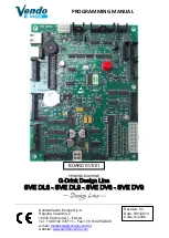
Melter equipment displays
Macro 200 melters have two displays built into their control panel, with three
sets of 7 segments each for displaying the temperature values (set point and
real temperature), programmable parameters and alarms.
They are equipped with LED indicators to display the heating of each
component, as well as the pump activations and the main machine connection
signal.
They are also equipped with LEDs indicating equipment connection/
disconnection and standby function connection/disconnection:
LED display
Component heating
Component status
constantly lit
constant
low temperature
blinking slowly
as need (according to PID parameters)
temperature near set point
blinking rapidly
programming or display
change in set point values
off
not heating
temperature reached
LED display
On/off
Standby
constantly lit
turned off unit
function activated
blinking slowly
deactivation programmed for the
current day
activation programmed for the
current day
blinking rapidly
activation/deactivation program-
ming mode
activation/deactivation program-
ming mode
off
unit in operation
function deactivated
simultaneous intermittence from leds of
pump activation and main machine signal timing in progress, once the tank has reached its set point temperature
Summary of Contents for MACRO 200
Page 1: ...ADHESIVE MELTER MACRO 200 INSTRUCTIONS MANUAL MA 5068 ENG 221220 GLUING SOLUTIONS ...
Page 8: ...FOCKE MELER GLUING SOLUTIONS TABLE OF CONTENTS This page is intentionally left blank ...
Page 32: ...FOCKE MELER GLUING SOLUTIONS INSTALLATION 3 12 This page is intentionally left blank ...
Page 66: ...FOCKE MELER GLUING SOLUTIONS 5 8 MAINTENANCE This page is intentionally left blank ...
Page 71: ...ELECTRICAL DRAWINGS 7 1 MA 5068 ENG MACRO 200 INSTRUCTIONS MANUAL 7 ELECTRICAL DRAWINGS ...
Page 72: ...FOCKE MELER GLUING SOLUTIONS 7 2 ELECTRICAL DRAWINGS This page is intentionally left blank ...
Page 74: ...FOCKE MELER GLUING SOLUTIONS 8 2 PNEUMATIC DIAGRAM This page is intentionally left blank ...
Page 82: ...FOCKE MELER GLUING SOLUTIONS 9 8 SPARE PARTS LIST This page is intentionally left blank ...