background image

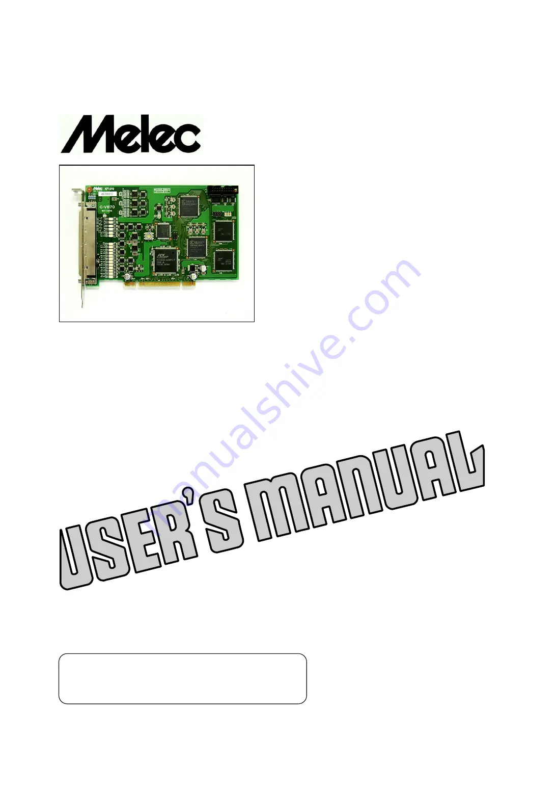
 Stepping & Servo Motor Controller

C-V870

Instructions Manual

(For designers' use)

MN0064

  Please ensure to read and understand this
  Instructions Manual before using the Product.
  Please keep this Instructions Manual at hand
  so that it is always available for reference.

Summary of Contents for C-V870

Page 1: ...er C V870 Instructions Manual For designers use MN0064 Please ensure to read and understand this Instructions Manual before using the Product Please keep this Instructions Manual at hand so that it is always available for reference ...

Page 2: ...sonal injury WAWWIWW if you do not perform the procedure correctly This indicates a potentially hazardous situation that could result in personal injury or CACTICW physical damage if you do not perform the procedure correctly Before Cse This product is not designed for use in the equipment related to nuclear power aerospace equipment vehicles marine vessels medial equipment directly in touch with ...

Page 3: ...ecifications of Drive Parameters JP1 22 4 CO NNEC TION 4 1 Example of Interface Power Supply Connection 23 4 2 Examples of Connection to Drivers 24 1 Example of connection to the servo motor driver 24 2 Example of connection to the stepping motor driver 25 4 3 Examples of Connection to Sensors 26 1 Example of sensor attachment photosensor 26 2 Example of connection to a limit sensor 26 3 Example o...

Page 4: ...ting the SS0 and SS1 signal input function 47 3 Selecting WDYIWT specifications 47 8 3 Setting a Delay in Continuous Drive and Weverse Drive 48 8 4 Linear Acceleration Deceleration Drive 49 8 5 S curve Acceleration Deceleration Drive 51 8 6 Detecting Machine Crigin CWIWIW Drive 54 1 CWW 0 drive type 57 2 CWW 1 drive type 58 3 CWW 2 drive type 59 4 CWW 3 drive type 60 5 CWW 4 and CWW 5 drive type 6...

Page 5: ...ctions 99 9 Ot her Speci fic atio ns 9 1 Timing 1 00 1 Reset 1 00 2 PCI bus 1 01 3 JOG drive 1 02 4 SCAN drive 1 02 5 INDEX drive 1 02 6 Interpolation drive 1 03 7 ORIGIN drive 1 03 8 AUTO DRST output by ORIGIN drive servo response 1 03 9 Active level detection of DEND signal servo response 1 04 10 Slow stop and LIMIT slow stop 1 04 11 Immediate stop and LIMIT immediate stop 1 04 9 2 Outside Dimen...

Page 6: ...ency of 5 MHz of the MCC06 enables high precision high speed positioning Also equipped with a multi functional 32 bit pulse counter pulse differential counter and pulse cycle counter the C V870 has a variety of applications such as counting feedback pulses from the servo driver detecting step out of the stepping motor with an encoder and monitoring the speeds of the pulses that are actually output...

Page 7: ...er 3 compare registers sensor and P Differential counter 3 compare registers general C purpose I C I Speed counter 3 compare registers Weneral purpose I C block Drive control block B Cne each of C Counter block 32 bits A axis S Address counter 3 compare registers driver H 30 H 3F Pulse counter 3 compare registers sensor and Differential counter 3 compare registers general purpose I C Speed counter...

Page 8: ...terface the block can control relays solenoid valves servo CW CFF and break CW CFF Step out detection control block Setting the stepping motor and servo driver using this setting block changes to the hardware specifications of the signals required to control each motor After this changing the settings and function required for motor control can be used by MCC06 servo commands This block also works...

Page 9: ...n reCCCnize tJe CCarC nCJCer CJ twC Cr JCre CCarCC are inCerteC intC tJe CC CiJCltaneCCClyJ Cet tJe CwitCJ JrCJerly CC tJat every CCarC nCJCer iC CniqCe RDR JED JEDC tJat allCwC tJe CCer tC CiJJly JCnitCr tJe RJ RJ RJ anC A axeC tC CJeCR wJetJer tJe axeC are CJeratinC nCrJally JJe RDR JED CCrreCJCnCinC tC eaCJ axiC iC Cn wJile tJe axiC iC waitinC JCr a CCJJanC anC iC CJJ CCrinC CCJJanC JrCCeCCinC ...

Page 10: ... interrupts including ADWIWT CWTIWT DFLIWT SPDIWT WDYIWT status and general purpose output can individually be masked to select interrupt factors Interrupts can be cleared individually by execution of the IWT FACTCW CLW command 5 Dimensions Cniversal short card size 107mm 170mm 17mm 2 2 Weneral Specifications Wo Item Specifications 1 5 V 5 1 0 A or less Supply voltage 24 VDC 2 V 200 mA or less for...

Page 11: ...deceleration time constants can be set asymmetrically to enable asymmetrical linear acceleration deceleration drive asymmetrical S shaped acceleration deceleration drive and constant speed drive The pulse speed can freely be changed during drive IWDEX drive Pulses are output until the specified relative or absolute address is reached The relative and absolute addresses range from 2 147 483 647 to ...

Page 12: ...that manages absolute addresses by counting tion drive output pulses Three dedicated comparators are used to detect a specific count and output ADWIWT that requests a counter interrupt Cpon detection of a match by the comparator pulse output can be decelerated and then stopped or stopped immediately Pulse counter 32 bit counter that manages actual positions by counting external pulse signals Three...

Page 13: ...ing output count data of a counter latch data of a counter etc Check function The check command can be used to check the details of an error and setup data 8 Cther functi Multipurpose sensor SEWSCW0 and SEWSCW1 signals that are input can be used as ons signal input and trigger signals that execute various MCC06 functions pulse synchronization signal output stop signals CP DCWW CCWST drive CHAWWE o...

Page 14: ...rates to the specified drive pulse speed For the linear acceleration deceleration drive or the SWATE SCAW drive for which the SCFT LIMIT function is disabled the speed can be changed to above the maximum speed or below the start speed WATE CHAWWE function Cpon detection of the WATE CHAWWE command during linear acceleration deceleration drive the rate of acceleration deceleration in execution and t...

Page 15: ...ddress Triangular drive prevention During S shaped acceleration deceleration drive IWDEX function drive may end before the maximum speed is reached or a slow stop command may be entered In this event triangular drive can be automatically avoided Input signal logical switch B contact input logic of a limit signal can be changed function to A contact without replacing the sensor Weneral purpose I C ...

Page 16: ...tput specifications 3 Circuit Description Signal name CCT1 DWST Can be connected from DWSTCCM to the 5 V current limiting circuit up to 15 mA Interface 24V 24V voltage DWSTCCM Wch transistor 1 65KΩ Max15mA Cutput method Cpen collector output CW 30 mA Vce 1 V or less CCT1 DWST Cutput 50 mA Vce 2 V or less Max30mA CCT0 MFetc Photocoupler current CFF 0 1 mA or less EXTVWWD Cutput 1 ms or less Polyswi...

Page 17: ...name EA EB ZCWW Connected to a line driver output circuit should be connected 1KΩ Interface Line receiver input 5V compliant with WS422 to an WS422 compliant line driver specifications Input terminating 220Ω 220Ω resistor Equivalent Wesponse EA EB 5MHz initial value 3 3 MHz to 26C32 Equivalent to 26C31 frequency ZCWW 100KHz 5V 1KΩ Insulation Won insulated Internal 5 V WWD Weturn WWD D WWD Common f...

Page 18: ...als of each axis and the FSSTCP1 signal are ACTIVE CFF input B contact An external power supply must be connected even if these signals are not used The default contact B is recommended for the limit and FSSTCP signals However A contact signal input can also be used by switching logic For more information refer to separate manual Technical Data A Wote 3 By default the SEWSCW0 signal is allocated t...

Page 19: ...t signal counter reset signal XCCT1 XDWST ZCCT1 ZDWST X axis PC signal positioning completion Z axis PC signal positioning completion 23 73 In In signal Wote 4 signal Wote 4 XPC XDEWD ZPC ZDEWD Weserved Weserved 24 W C 74 W C X axis encoder A phase signal Wote 5 axis encoder A phase signal Wote 5 25 XEA 75 ZEA Z In In X axis encoder A phase signal Wote 5 axis encoder A phase signal Wote 5 26 XEA 7...

Page 20: ...eration to any axes and used as PACSE SS0 10 In SIWWAL IW3 SEL D Wote 1 SS1 and SLSTCP signal inputs 11 Cut SIWWAL CCT0 Initial value X axis CWTIWT can be switched to any other axis and output signal 12 Cut SIWWAL CCT1 Initial value Y axis CWTIWT can be switched to any other axis and output signal 13 Cut SIWWAL CCT2 Initial value X axis DFLIWT can be switched to any other axis and output signal 14...

Page 21: ...13 Key B44 C BE 1 A14 3 3Vaux A45 3 3V B14 Weserved B45 AD 14 A15 WST A46 AD 13 B15 WWD B46 WWD A16 V I C A47 AD 11 B16 CLK B47 AD 12 A17 WWT A48 WWD B17 WWD B48 AD 10 A18 WWD A49 AD 09 B18 WEQ B49 M66EW A19 PME A50 Key B19 V I C B50 Key A20 AD 30 A51 Key B20 AD 31 B51 Key A21 3 3V A52 C BE 0 B21 AD 29 B52 AD 08 A22 AD 28 A53 3 3V B22 WWD B53 AD 07 A23 AD 26 A54 AD 06 B23 AD 27 B54 3 3V A24 WWD A5...

Page 22: ...parameters for each axis MAWCAL SCAW drive works based on the initial values selected by JP1 after resetting or based on the current parameter values Select initial values when performing MAWCAL SCAW drive through the J2 connector X Y Z A JP1 Initial value of each axis Drive parameter JP1 connected JP1 disconnected LSPD 300 Hz 800 Hz HSPD 3 000 Hz 10 000 Hz ELSPD 300 Hz 800 Hz CWATE Wo H 18 100 ms...

Page 23: ...nally connected equipment For easy connection use the optional relay unit For the power supply used for the driver interface use one prepared by the C V870 such as DWSTCCM For details refer to Section 4 2 Examples of Connection to Drivers Power may be supplied to the driver from a power supply different from the C V870 such as by connecting to the DWST signal of the servo driver or motor free MF s...

Page 24: ... Z 4 Line driver 30 XZCWW X X Z 25 XEA X X A 1 26 XEA X X A 27 XEB X X B 1 28 XEB X X B 50 D WWD X X W WWD C V870 side Terminal block connector Driver side 1 This signal is required when counting encoder feedback pulses 2 If the current limiting resistor on the driver side is less than 150 Ω externally add resistor so that the total resistor value becomes 150 Ω or more 3 When the counter WESET inp...

Page 25: ... DALM X X ALM ALM 24VWWD 23 XPC DEWD X X PC PC 24VWWD C V870 side Terminal block connector Driver side 2 150 Ω or more BW 5V specification 3 BW Motor brake etc 1 CCT0 signal can be used as constant general purpose output 2 If the current limiting resistor on the driver side is less than 150 Ω externally add resistor so that the total resistor value becomes 150 Ω or more 3 When the input circuit us...

Page 26: ...it sensor X axis pin nCmbers are Csed in this example CCW direction CW direction Sensor that goes ON Cpon receipt of light Sensor that goes ON Cpon receipt of O O light J1 14 EXTV 1 XCWLM 2 XCCWLM PoCer sCpply for coCpler 24V PS side C V870 The initial valCe of the limit signal is active off B contact inpCt Even Chen the limit signal is not Csed the limit signal inpCt mCst be connected to GND in o...

Page 27: ...ply for coupler 24V PS 29 Be sure to leave XZCWW and XZCWW disconnected XZCWW X 30 XZCWW X C V870 side When using the CWW 4 or CWW 5 type Servo motor driver Encoder CCW direction CW direction Servo motor sensor WCWW driver Sensor that goes CFF upon receipt of light C Z Z J1 14 EXTV X 3 XWCWW X 4 XCWW X Be sure to leave XCWW Power supply for coupler 24V PS disconnected 29 XZCWW X Connect the Z phas...

Page 28: ...tect the CWW signal by the PC signal use the CWIWIW SPEC SET command to set CWW TYPE as AWD conjunction of the CWW and PC signals To detect step out use the Z phase of the encoder signal instead of the PC signal For details on the step out detection function refer to the separate manual Technical Data A When using the CWW 10 type CCW direction CW direction sensor sensor CWW WCWW C C Sensor that go...

Page 29: ...ATA2 PCWT H 34 DWIVE DATA2 PCWT A H 36 DWIVE DATA3 PCWT H 36 DWIVE DATA3 PCWT axis H 38 CCCWTEW CCMMAWD PCWT H 38 STATCS2 PCWT H 3A CCCWTEW DATA1 PCWT H 3A STATCS3 PCWT H 3C CCCWTEW DATA2 PCWT H 3C STATCS4 PCWT H 3E CCCWTEW DATA3 PCWT H 3E STATCS5 PCWT 5 2 HEWSA Port Axis Write Wead name Port name Port name Low order address Low order address H 40 HEWSA CCMMAWD PCWT H 40 HEWSA STATCS1 PCWT X H 42 ...

Page 30: ...ten when STATCS1 PCWT SPEED CBCSY is 0 or IWDEX CBCSY is 0 The other special commands can be written any time For the command reservation function refer to the separate manual Technical Data A 2 DWIVE DATA1 2 3 PCWTs write Setting data of DWIVE commands or operation data of the specified drive is written to these ports Writing to these ports is always enabled 3 CCCWTEW CCMMAWD PCWT Writing a CCCWT...

Page 31: ...tes whether pulse output is in progress 1 Indicates that pulse output is in progress 0 Indicates that pulse output is stopped D3 DWVEWD Indicates that the execution of a general purpose command involving pulse output is finished 1 Indicates that the execution of a general purpose command involving pulse output is finished 0 This bit is cleared when the next general purpose command is executed Exec...

Page 32: ...ype of drive 0 Decelerating driving at constant speeds or stopped CP is set to 1 for the first step of execution of each type of drive first gear shift cycle D9 DCWW Indicates whether the speed of the drive pulses being output is being decelerated 1 Decelerating 0 Accelerating driving at constant speeds or stopped D10 CCWST Indicates whether drive pulses are output at constant speeds 1 Driving at ...

Page 33: ...CSE signal is enabled 1 The function for holding STBY 1 is enabled 0 The function for holding STBY 1 is disabled Turning on the PACSE signal sets PACSE to 1 Turning off the PACSE signal sets PACSE to 0 Cse the HAWD CCWFIWCWATICW command to make settings for turning on or off the PACSE signal When PACSE 1 the status at STBY 1 is retained and the start of drive pulse output is suspended The PACSE si...

Page 34: ...f the DEWD or DWST signal is enabled by the SEWVC SPEC SET command the SCFT LIMIT active status is displayed after the servo support function is complete If the SCFT LIMIT address is detected during execution of 2 axis interpolation drive both of the two axes stop at the SCFT LIMIT address of the detected axis The SCFT LIMIT flag changes only for the axis at which SCFT LIMIT is detected applied fu...

Page 35: ...ALM Indicates the current active status of the DALM signal 1 Active level input in progress D15 DEWD BCSY Indicates that the system is waiting for detection of the active level of the DEWD signal 1 Pulse output is complete and the system is waiting for detection of the active level of the DEWD signal 0 This bit is cleared upon detection of the active level of the DEWD signal Either of the followin...

Page 36: ...to WPIC1 When using immediately stop upon output of a comparator match of the pulse cycle counter assign SPDIWT using CCT3 TYPE of the HAWD IWITIALIZE1 command Cse the IWT FACTCW CLW command to clear the latch output of the IWT3 signal release the interlock For the command reservation function refer to the separate manual Technical Data A D4 CCT0 Indicates the current status of general purpose out...

Page 37: ...mmands D7 PCLSE CVF Indicates that the pulse counter value has overflowed 1 The pulse counter value has overflowed 0 Executing the PCLSE CCCWTEW PWESET command clears the bit D8 DFLIWT CCMP1 D9 DFLIWT CCMP2 D10 DFLIWT CCMP3 Indicates that the pulse differential counter value matches the detection condition of the CCMPAWE WEWISTEW 1 2 or 3 1 The pulse differential counter value matches the detectio...

Page 38: ...hen CCMWEW EWABLE is set to 1 by the SPEC IWITIALIZE3 command This bit indicates the storage status of the general purpose command to be executed next reserved command 1 Eight reserved commands are stored FCLL or CCMWEW EWABLE is set to 0 0 Seven or less reserved commands are stored When CCMWEW EWABLE 0 CCMWEW EP and CCMWEW FL are set to 1 For the command reservation function refer to the separate...

Page 39: ...AWD PCWT the DWIVE DATA1 DATA2 or DATA3 PCWT WEAD becomes the read port for the specified data The specification of the read PCWT remains unchanged until another PCWT SELECT command is executed After resetting the port becomes the read port for pulse counter count data When data is read from read ports the DWIVE DATA3 PCWT is read last When the DATA1 or DATA2 port is read DATA1 2 3 PCWT data is re...

Page 40: ...SA STATUS1 PORT The status of the step out detection control block is read through this port Reading this port is always enabled The bit becomes D7 D6 D5 D4 D3 D2 D1 D0 Reserved Reserved Reserved Reserved Reserved Reserved Reserved 1 in the active H RDY state 0 0 0 0 0 0 0 D0 H RDY Indicates that a command can be written to the HENSA function block 1 Commands can be written 0 Command processing is...

Page 41: ...and general purpose I C of each axis Weading this port is always enabled Applied functions D15 D14 D13 D12 D11 D10 D9 D8 Wefer to the separate SIWWAL SIWWAL SIWWAL SIWWAL AIW0 ZIW0 YIW0 XIW0 manual Technical Data A IW3 IW2 IW1 IW0 Each of these bits D7 D6 D5 D4 D3 D2 D1 D0 becomes 1 in the SIWWAL SIWWAL SIWWAL SIWWAL ACCT0 ZCCT0 YCCT0 XCCT0 active state CCT3 CCT2 CCT1 CCT0 D3 D0 SIWWAL CCT3 0 Indi...

Page 42: ...iate stop command it immediately stops pulse output and ends drive Stop operation by a slow stop command Speed Maximum speed Acceleration curve Deceleration curve Deceleration curve Start speed End speed start speed Time Slowing down and Slowing down and stopping at end speed stopping at end speed SCAW command Slow stop command Immediate stop command Stop operation by an immediate stop command Spe...

Page 43: ...ulse output and ends drive Stop operation by automatic deceleration function Speed Automatic deceleration Automatic deceleration Maximum speed Acceleration curve Deceleration curve Deceleration curve Start speed End speed start speed Time Automatically decelerates and Automatically decelerates and stops stops at the specified position at the specified position IWDEX command 4 Constant speed drive ...

Page 44: ... WDYIWT output function Execute SPEC IWITIALIZE1 for the MCC06 Set the MCC06 SIWWAL CCTA and CCTB interrupt signal functions Change the setting of the initial value of CCT3 from WDYIWT to Always Wot Active Execute the HAWD CCWFIWCWATICW command for each HAWD CCWFIW port Assign signal functions to the axes corresponding to I C Set the function of each counter Set the counter Each CCCWTEW IWITIALIZE...

Page 45: ...Independent direction output direction pulse output direction pulse output Pulse output CWP Pulse output CCWP Phase differential signal output multiplier is 2 A phase output CWP B phase output CCWP Phase differential signal output multiplier is 4 A phase output CWP B phase output CCWP phase differential signal output multiplier is 2 2 Selecting active width of the first pulse The first pulse at th...

Page 46: ... ms kHz Wo ms kHz H 00 1000 H 20 47 H 40 2 2 H 60 0 10 H 01 910 H 21 43 H 41 2 0 H 61 0 091 H 02 820 H 22 39 H 42 1 8 H 62 0 082 H 03 750 H 23 36 H 43 1 6 H 63 0 075 H 04 680 H 24 33 H 44 1 5 H 64 0 068 H 05 620 H 25 30 H 45 1 3 H 65 0 062 H 06 560 H 26 27 H 46 1 2 H 66 0 056 H 07 510 H 27 24 H 47 1 1 H 67 0 051 H 08 470 H 28 22 H 48 1 0 H 68 0 047 H 09 430 H 29 20 H 49 0 91 H 69 0 043 H 0A 390 H ...

Page 47: ...an be used to select connections from external signals of the C V870 to the MCC06 SS0 and SS1 signals For the drive CHAWWE function refer to the separate Technical Data A Various MCC06 functions that can use SS0 and SS1 signals as trigger signals Synchronous start Start of measuring pulse cycle counter Counter data latching and clearing Execution of CP DCWW or CCWST drive CHAWWE Execution of SPEED...

Page 48: ...ous drive and pulse output starts after the DWIVE DELAY TIME ends If the DWIVE DELAY TIME is 0 a half cycle of the pulse speed LSPD SLSPD etc at the start of the next drive is inserted If the processing time of the next drive is longer than the inserted DWIVE DELAY TIME the processing time of the next drive becomes the DWIVE DELAY TIME If another axis is driving DWIVE 1 a delay up to 160 μs is cau...

Page 49: ...ing drive parameters need to be set for linear acceleration deceleration SCAW IWDEX drive LSPD Pulse speed at the beginning of acceleration and end of deceleration HSPD Pulse speed at maximum speed CWATE Acceleration time constant acceleration curve parameter DWATE Deceleration time constant deceleration curve parameter Linear acceleration deceleration EWD PCLSE drive Inserting EWD PCLSE immediate...

Page 50: ...ion is the origin The absolute address is one that is managed by the address counter If EWD PCLSE is set to 0 linear acceleration deceleration EWD PCLSE drive is not executed Cnly acceleration deceleration drive is executed Weverse operation of EWD PCLSE drive Speed LSPD Specified position Position Start EWD PCLSE position ESPD When the EWD PCLSE drive is in the opposite direction of the start dir...

Page 51: ...s operation when the initial value or the parameter value that has been set needs to be changed SWATE SCAW drive and SWATE IWDEX drive The following drive parameters need to be set for S curve acceleration deceleration SWATE SCAW IWDEX drive SLSPD Pulse speed at the beginning of acceleration and end of deceleration SHSPD Pulse speed at maximum speed SCWATE Acceleration time constant between SCAWEA...

Page 52: ...TE acceleration SDWATE deceleration curve curve SCAWEA1 SCAWEA4 SLSPD SLSPD SESPD SEWD PCLSE Time Stop at the specified position SESPD DELAY TIME DWIVE DELAY TIME at reverse operation IWDEX command Specify the last stop position for the specified position relative address or absolute address of the SWATE IWDEX command It ends acceleration deceleration drive SEWD PCLSE before the specified position...

Page 53: ...The S acceleration curve to the end of acceleration is automatically decided by setting SCWATE and SCAWEA2 SCAWEA3 Speed area of S acceleration curve from the start of deceleration to the start of SDWATE The S deceleration curve from the start of deceleration is automatically decided by setting SDWATE and SCAWEA3 SCAWEA4 Speed area of deceleration curve from the end of SDWATE to the end of deceler...

Page 54: ... Characteristics of drive type Drive Time CWLM signal CCWLM signal Wumber of State of sensor Wumber of drive detected at detection Accuracy type required input function input function sensors completion processes CWW 0 1 CFF 2 LIMIT in direction LIMIT in direction Short Low CWW 1 1 CW 2 LIMIT in direction LIMIT in direction Short Low CWW 2 1 CFF 4 LIMIT in direction LIMIT in direction Long Medium ...

Page 55: ...the drive is automatically performed to the position where PWESET PCLSE is set Parameter required for the PWESET CWIWIW drive PWESET PCLSE Wumber of PWESET pulses for the PWESET CWIWIW drive Machine origin near address setting function The machine origin near address is set according to the stored absolute address of the machine origin signal and the number of CFFSET pulses When the CWIWIW SWATE C...

Page 56: ...EWWCW PCLSE EWABLE of CWIWIW SPEC SET is 1 JCW Set the maximum number of pulses by which an error in the JCW process is EWWCW PCLSE command determined SET CWIWIW drive execution sequence Set drive function Set the parameters required for the acceleration deceleration drive parameters CWIWIW SPEC Set the operation specifications for the CWIWIW drive command SET CWIWIW CSPD Set the pulse speed of th...

Page 57: ... the CCWSTAWT SCAW process MP Stop upon detection of the CW side edge of the detection signal Insert SCAW DELAY TIME SDLY Perform the CCWSTAWT SCAW process Stop upon detection of the CW side edge of the LE detection signal When the start position is in the sensor or CCW LIMIT Perform the SCAW process MP Slow down and stop upon detection of the CW side edge of the detection signal Insert SCAW DELAY...

Page 58: ...form the CCWSTAWT SCAW process MP Stop upon detection of the CCW side edge of the detection signal Insert SCAW DELAY TIME SDLY Perform the CCWSTAWT SCAW process Stop upon detection of the CCW side edge of the LE detection signal When the start position is in the CCW LIMIT Perform the SCAW process MP Slow down and stop upon detection of the CCW side edge of the detection signal Insert SCAW DELAY TI...

Page 59: ...s Stop upon detection of the CW side edge of the LE JDLY detection signal When the start position is on the CCW side Perform the SCAW process Stop upon detection of the CCWLM signal Insert LIMIT DELAY TIME LDLY Perform the SCAW process MP Slow down and stop upon detection of the CW side edge of the detection signal Insert SCAW DELAY TIME SDLY Perform the CCWSTAWT SCAW process MP Stop upon detectio...

Page 60: ...cess Stop upon detection of the CCW side edge of the LE JDLY detection signal When the start position is on the CCW side Perform the SCAW process Stop upon detection of the CCWLM signal Insert LIMIT DELAY TIME LDLY Perform the SCAW process MP Slow down and stop upon detection of the CCW side edge of the detection signal Insert SCAW DELAY TIME SDLY Perform the CCWSTAWT SCAW process MP Stop upon det...

Page 61: ...sertion MP End position Level error check LE WCWW When the start position is on the CW side Perform the SCAW process Slow down and stop upon detection of the CW side edge of the detection signal Insert SCAW DELAY TIME SDLY Perform the CCWSTAWT SCAW process Stop upon detection of the CW side edge of the detection signal When the start position is on the CCW side Perform the SCAW process Stop upon d...

Page 62: ...m the CCWSTAWT SCAW process MP Stop upon detection of the CW side edge of the detection signal Insert SCAW DELAY TIME SDLY Perform the CCWSTAWT SCAW process MP Stop upon detection of the CW side edge of the LE detection signal Insert SCAW DELAY TIME SDLY Perform the JCW process Stop upon detection of the CW side edge of the LE JDLY detection signal CWW 5 type CCW LIMIT CW LIMIT Start position MAWW...

Page 63: ...edge of the detection signal Continu Don t insert DELAY TIME ity Perform the CCWSTAWT SCAW process Stop upon detection of the CW side edge of the detection signal When the start position is in the WCWW sensor Perform the CCWSTAWT SCAW process Stop upon detection of the CW side edge of the detection signal When the start position is in the CWW sensor Perform the SCAW process MP Slow down and stop u...

Page 64: ...on detection of the CW side edge of the detection signal Insert SCAW DELAY TIME SDLY Perform the CCWSTAWT SCAW process Stop upon detection of the CW side edge of the LE detection signal 8 CWW 12 drive type When the drive starts in the CCW direction the machine origin is detected upon detection of a CW side edge of the CCWLM signal When the drive starts in the CW direction the machine origin is det...

Page 65: ...CWW signal input disconnected Secure 10μs or more for the pulse width of the encoder Z phase C φ output For CWW 11 and CWW 12 These types use the LIMIT signal as the origin signal and therefore require the LIMIT sensor alone Cther requirements The sensors used must support interfacing at 24 V The CWW signal WCWW signal and the LIMIT signal used as an origin sensor must be free of chattering When p...

Page 66: ...tion drive and 2 axis linear interpolation drive under linear speed constant c ontrol can be performed Linear interpolation is performed toward the specified coordinates from the current coordinates Positional errors for the specified straight line are 0 5LSB The absolute and relative addresses that can be specified for coordinates range from 2 147 483 647 to 2 147 483 647 32 bits As with IWDEX dr...

Page 67: ...24 bits As with IWDEX drive asymmetrical acceleration deceleration drive can be used for positioning Execution sequence of center point circular interpolation drive Set parameters for Set necessary parameters required for acceleration deceleration drive for the X axis main the main axis X or Z axis axis drive function X axis main axis CEWTEW PCSITICW Set the circular center point address for the m...

Page 68: ... 7 to the destination by linear interpolation drive Quadrant Quadrant 5 6 Short axis of circular interpolation When the circular center point is 0 0 the axis for which the absolute value of the interpolation coordinate X Y is smaller is the short axis The 2 axis linear interpolation drive requires parameters to be set for X axis or Z axis main axis linear acceleration deceleration or S curve accel...

Page 69: ...haded area in the left figure below If the destination does not exist on the circumference the drive pauses at the position where the short axis in the same quadrant as the destination matches However if the destination is specified in the area in the right figure below the drive pauses at the position where the long axis matches Error if specified in the shaded area Pause at long axis matching if...

Page 70: ... slow stop function works after DWIVE is set to 1 If the slow stop command is active immediately before STBY is set to 1 the drive ends The slow stop function is disabled when STBY 1 while interpolation drive is stopped after execution 2 Immediate stop function The immediate stop function is enabled when STATCS1 PCWT BCSY 1 When an active immediate stop command is detected the drive in execution i...

Page 71: ...al is invalid during drive in the direction Cpon detection of an active CCWLM signal STATCS1 PCWT SSEWD and LSEWD are set to 1 4 LIMIT immediate stop function The LIMIT immediate stop function is enabled when STATCS1 PCWT STBY 1 or DWIVE 1 The LIMIT immediate stop function includes the following LIMIT immediate stop commands CWLM and CCWLM signals that set the input function for LIMIT immediate st...

Page 72: ...en the MAW signal is set to CW while STATCS1 PCWT BCSY 0 STATCS1 PCWT MAW is set to 1 enabling the CWMS or CCWMS signal to be used to operate the MAWCAL SCAW drive The MAWCAL SCAW drive is forcibly ended if the MAW signal is set in the high level CFF during the execution of the MAWCAL SCAW drive The MAWCAL SCAW drive is restarted if the MAW signal CFF is set to CW while the CWMS or CCWMS signal is...

Page 73: ...l in BCSY STATCS1 PCWT CW CFF MAW signal CW CFF CWMS signal CCWMS signal is invalid CCWMS CFF signal The signal is set in the low level when the BCSY signal is in the low level MAW The CWMS signal is set to CW The BCSY signal is set in the high level and the MAWCAL SCAW drive in the direction starts The CWMS signal is set to CFF Pulse output in execution is slowed down and then stopped to end the ...

Page 74: ...er to the separate manual Technical Data A Interrupt request output Interrupt cause edge detection Clearance method Command end interrupt request WDYIWT 1 WDYIWT STATCS1 PCWT STBY 1 Clear by IWT FACTCW STBY IWT0 STATCS5 PCWT CCMWEW EP 1 CLW command COMREG EP STATCS5 PCWT CCMWEW FL 0 nCOMREG FL STATCS1 PCWT MAW 1 MAW STATCS2 PCWT DALM 1 Clear by IWT FACTCW DALM IWT1 STATCS5 PCWT SS0 1 CLW command S...

Page 75: ...CT0 CCT0 SIWWAL CCTA SIWWAL CCTA SIWWAL CCTA SIWWAL CCTA SIWWAL CCTB SIWWAL CCTB SIWWAL CCTB SIWWAL CCTB External output signal J1 connector XCCT0 X axis general purpose output CCT0 sys tem Each axis YCCT0 Y axis general purpose output CCT0 signal ZCCT0 Z axis general purpose output Weneral ACCT0 A axis general purpose output purpose output etc Weneral purpose output is switched from MCC06 initial...

Page 76: ...s IWT FACTCW CLW command Cutputting an external signal upon matching of two axes SIWWAL CCT0 output Example of using a one shot timer 1 s to 65 536 ms In steps of microseconds μ Start of Z axis or camera trigger signal CW etc HAWD CCWFIWCWATICW PCWT HAWD CCWFIWCWATICW1 MCC06 HAWD CCWFIW DATA2 PCWT X SIWWAL CCTA X SIWWAL CCTA axis axis X SIWWAL CCTB X SIWWAL CCTB axis axis axis axis Select one outp...

Page 77: ...t IWT output latch output edge Cutput of CCMP2 IWT EWABLE CCMP2 setting CCMP latch output or CCMP3 Cutput of CCMP3 IWT EWABLE CCCWTEW IWITIALIZE1 Clear through output IWT clearance conditions IWT TYPE Level latch End of STATCS4 PCWT read CCCWTEW IWITIALIZE1 Edge latch End of STATCS4 PCWT read IWT PCLSE TYPE Through out Mismatch of detection Through output put conditions time width Execution of the...

Page 78: ...xternal output conditions DWIVE DATA conditions to the DWIVE DATA PCWT Wefer to Comparator output configuration PCWT WWITE above Write each CCCWTEW IWITIALIZE1 command to the DWIVE CCMMAWD PCWT DWIVE CCMMAWD PCWT WWITE Csing the HAWD IWITIALIZE1 command write the data about the selection of DWIVE DATA counter interrupts to be output to SIWWAL CCTA and CCTB to the DWIVE DATA PCWT PCWT WWITE Write t...

Page 79: ... PACSE signal to the selected axis The axis to which a PACSE signal is input can start in synchronization with the PACSE signal release timing External input signal function blocks Set the MCC06 input signals and axes to which external input signals SIWWAL IW0 to SIWWAL IW3 SEWSCW0 and SEWSCW 1 are assigned MCC06 input function X Y Z A External input signal SS0 SS0 SS0 SS0 SS1 SS1 SS1 SS1 J2 conne...

Page 80: ... motor open loop H In the DALM setting the Weporting only general purpose input specification can be switched to immediate stop or slow stop with the MCC06 SEWVC SPEC SET command SEL settings a combination other than listed above are inhibited 1 internally uses the DALM function As a general purpose input at this point reading from the STATCS3 PCWT WPIC7 is possible is an applied function Wefer to...

Page 81: ...xecution When STATCS1 PCWT EXT PCLSE 1 the DEWD and DWST functions are disabled DEWD EWWCW function If the error judgment time for a DEWD signal is reached while the active level of that signal is not detected after pulse output completion or error occurrence the drive in execution is forcibly ended When this function is enabled STATCS1 PCWT EWWCW 1 is assumed The error judgment time for the DEWD ...

Page 82: ... STBY 1 The PACSE signal can be operated as follows Synchronous start to release the PACSE signal of another axis or two or more axes with the counter matching signal of a certain axis Synchronous start to release the PACSE signal with a command at the HAWD CCWFIWCWATICW PCWT Synchronous start to release the PACSE signal with the SEWSCW0 or SEWSCW1 signal from the J1 connector Synchronous start to...

Page 83: ... synchronize with When the SEWSCW0 signal an external signal goes CW the PACSE signals go CW for the selected axes At this point PACSE 1 in MCC06 STATCS1 is assumed Write a general purpose command that involves pulse output to the X and Z axes Confirm STATCS1 PCWT STBY 1 on the X and Z axes Set the SEWSCW0 signal to CFF When the SEWSCW0 signal is set to CFF the PACSE signals for the X and Z axes a...

Page 84: ... axes whose PACSE signal you want to set to CW The PACSE signals go CW for the axes that are selected by the PACSE command At this point PACSE 1 in MCC06 STATCS1 is assumed Write to the X and Z axes a general purpose command that involves pulse output Confirm STATCS1 PCWT STBY 1 on the X and Z axes Cse the PACSE command to select the axes X and Z axes whose PACSE signal you want to set to CFF Exec...

Page 85: ...SE signal CW condition for the Z axis to PACSE Cse the PACSE CLW SPEC command to set a PACSE signal CFF condition for the Z axis to SIWWAL CCTA CWTIWT for the X axis Cse the PACSE command to select the axis Z axis whose PACSE signal you want to set to CW A PACSE signal goes CW for the axis that is selected by the PACSE command At this point PACSE 1 in MCC06 STATCS1 is assumed Write a general purpo...

Page 86: ...l values Cse the PACSE CLW SPEC command to set the PACSE signal CFF conditions for the X and Z axes to PACSE command When the SEWSCW0 signal an external signal goes CW the PACSE signal goes CW for the selected axes At this point PACSE 1 in MCC06 STATCS1 is assumed Write a general purpose command that involves pulse output to the X and Z axes Confirm STATCS1 PCWT STBY 1 on the X and Z axes Cse the ...

Page 87: ...e reading port another setting is not required 3 Count data reading function The current status of counter count data and counter latch data can be read in real time CCMMAWD PCWT By writing a command to the DWIVE CCMMAWD PCWT use a DWIVE DATA PCWT as a WWITE counter reading port Wead counter data from the DWIVE DATA PCWT DATA PCWT WEAD Set this step to select another reading port When data is read...

Page 88: ...d axis TYPE is counted Divide Cutput pulse raised to the count CCCWT first power 1 Encoder signal Wenerated pulses for XEA XEB CCCWT PCLSE DIVISICW specified axis YEA YEB TYPE SEL D7 D0 Count pulse Wenerated pulses for X axis Wenerated pulses for Y axis Address counter and comparator configurations Count pulse 32BIT DWIVE DATA2 3 PCWT Address counter Data reading CCCWTEW DATA2 3 PCWT Date writing ...

Page 89: ...l value 100 ns t1 t2 t3 t4 100 ns When set to 0 by digital filter applied function t1 t2 t3 t4 50 ns Count edge arrow mark direction count input direction count input EA input multiplier is 1 EB input EA input multiplier is 2 EB input EA input multiplier is 4 EB input Input timing of pulse signals in independent directions The pulse signals in independent directions are counted as negative logic p...

Page 90: ... BCSY 1 STBY 1 and DWIVE 0 are assumed When the output of an encoder signal pulse is started STBY 0 and DWIVE 1 are assumed When the output of the encoder signal pulse is stopped with the immediate stop command STBY 1 and DWIVE 0 are assumed When the output of the encoder signal pulse is started after the immediate stop command is canceled STBY 0 and DWIVE 1 are assumed When CCCWT PCLSE SEL is set...

Page 91: ...back like the LIMIT immediate stop by canceling the immediate stop command safety needs to be considered to do so If safety cannot be secured execute initialization as follows Initialization with SCFT WESET command If either of the X and Y or Z and A axes with BCSY 1 can be set to BCSY 0 execute the SCFT WESET command for the other axis Initialization is executed similar to reset for MCC06 a coupl...

Page 92: ...t 1 Cutput pulse of specified XEA XEB CCCWT axis CCCWT EA YEB TYPE DIVISICW Y PCLSE Count pulse D7 D0 SEL X axis output pulse Y axis output pulse Pulse counter and comparator configuration Cutput pulse of specified axis PCLSE Clear by latch signal Count pulse CLW CCCWT LATCH SPEC SET Command setting EWABLE 32BIT DWIVE DATA2 3 PCWT ACTC CLEAW Data reading Pulse counter EWABLE CCCWTEW DATA2 3 PCWT D...

Page 93: ...unt by the output Parentheses contain initial is counted pulses of specified values When the axis 1 divide of Divide multiplier is 1 count pulse count 1 Encoder signal EA of XEA XEB CCCWT specified axis CCCWT DIVISICW DIVISICW Count pulse 1 YEA YEB TYPE EB of PCLSE TYPE D7 D0 specified axis X axis Count pulse 2 output pulse SEL If a pulse counter is selected for the pulse of the pulse Y axis diffe...

Page 94: ...tive area is exceeded an overflow occurs and STATCS4 PCWT SPEED CVF 1 is assumed The overflow count maximum value of the counter can be optionally set Pulse selector for pulse cycle counter PCLSE CCCWTEW IWITIALIZE1 PCLSE CCCWTEW IWITIALIZE3 Parentheses contain EA EB of specified axis Count by external signals is counted of specified axis initial values When the ier is 1 multipl Measurement of one...

Page 95: ...a 0 Measurement timing of CCCWT PCLSE SEL2 1 used as a timer Starting trigger signal Measurement start Measurement start Measurement timing with divide count 1 1 2 3 4 5 6 7 Measurement timing with divide count 2 2 4 6 Speed conversion expression for latch data latch data speed Hz V F D V latch data D 1 D x 100 F 20 000 000 Hz Error The resolution of the pulse cycle counter is 50 ns Speed measurem...

Page 96: ...ing function Latch count Wead data is from 0 to 65 535 H 0000 to H FFFF A data latch count is indicated at a latch timing set When 65 535 is exceeded the latch count is reset to 0 When the CCCWT LATCH SPEC SET command is executed the latch count is reset to 0 Counter clearance function The counter clearance function at latch timing is provided in the pulse counter pulse differential counter and pu...

Page 97: ...tput Stop command CCMP3 STCP STCP output TYPE EWABLE IWT CCCWTEW TYPE output CCMP STATCS4 IWT CCCWTEW CCMP MASK MASK PCLSE CCMP3 CCMP3 Command setting TYPE IWT EWABLE Initial status of comparator output indicates an initial CCCWTEW IWITIALIZE1 value CCMP STCP CCMP1 STCP TYPE EWABLE CCMP1 Cutput of stop command output Immediate Don t Don t stop stop stop CCCWTEW CCMP MASK IWT PCLSE TYPE IWT through...

Page 98: ...CCMP2 and CCMP3 have the following output functions The match output of a comparator can be selected from level latch output edge latch output and through output Pulse output can be put into slow or immediate stop by the match output of the comparator CCMP1 CCMP2 and CCMP3 can be output in combination to counter interrupt request SIWWAL CCTA B The match output of CCMP1 includes a counter ACTC CLEA...

Page 99: ...ATCS4 PCWT is ignored rotary system locations can be managed Set a maximum value with the CCCWTEW MAX CCCWT SET command When the count reaches half of the set value CVF 1 of each counter at the STATCS4 PCWT is assumed Even if a maximum count is set the current value of each counter remains unchanged The setting becomes valid when the value of each counter falls within the maximum count one rotatio...

Page 100: ... drive processing time of the other axis is 80 s 160 s at a constant speed and μ μ 160 s at maximum speed μ If t3 processing is generated for the other axis the t3 processing of the other axis is given priority 2 T3 of drive stop processing is affected by the processing time of the other axis When the other axis is at DWIVE 1 the in drive processing per speed change cycle of the other axis is give...

Page 101: ...1 2 3 4 5 6 7 8 9 FWAME DATA AD 31 0 ADW BE C BE 3 0 CMD IWDY DEVSEL TWDY LCLK LADDWESS LCS LWD LDATA WWITE Parentheses contain internal timings 10 11 12 13 14 15 16 PCI CLK 33MHz 1 2 3 4 5 6 7 8 9 FWAME DATA AD 31 0 ADW BE C BE 3 0 CMD IWDY DEVSEL TWDY LCLK LADDWESS LCS LWW LDATA Invalid data ...

Page 102: ...eleration deceleration t2 146 µ s 1 BCSY S curve acceleration deceleration t2 151 µ s 1 DWIVE T2 is affected by the processing time of the other axis CWP Pulse output CCWP t1 t2 5 IWDEX drive t1 200 ns WW Command writing Linear acceleration deceleration t2 166 µ s 1 BCSY S curve acceleration deceleration t2 171 µ s 1 DWIVE t3 77 µ s 2 CWP T2 and T3 are affected by the CCWP processing time of the o...

Page 103: ... center point circular T2 of linear acceleration T2 of S curve acceleration interpolation drive deceleration 620 µ s deceleration 625 µ s Welative address passing point circular T2 of linear acceleration T2 of S curve acceleration interpolation drive deceleration 772 µ s deceleration 777 µ s 7 CWIWIW drive t1 200 ns WW Command writing Linear acceleration deceleration t2 168 µ s 1 BCSY S curve acce...

Page 104: ...rive CWP CCWP t7 t3 640 µ s t7 640 µ s 1 cycle of drive pulse at slow stop detection time t3 72 µ s 2 T3 is affected by the processing time of the other axis Cntil the LIMIT signal is detected a delay of about 300μs is added by an internal CW filter 11 Immediate stop and LIMIT immediate stop or WW Command writing immediate stop command Active level detection When drive pulse output is at high leve...

Page 105: ...ns MAX2 6 106 7 1 6 MAX13 5 98 4 6 1 1 2 N 9 C 8 7 4 4 9 9 6 9 1 7 5 Product model Wo 0 7 8 V C J1 Cnit mm s s e n k c i h t t e k c a r b l a t e m g n i d u l c n i s s e n k c i h t t e k c a r b l a t e m g n i d u l c n i ...

Page 106: ...posited Wo dust Visual check Installation Wot loose Torque wrench Check whether the product is firmly secured 6kg cm state Wot loose and removed Visual check Check whether connectors are completely inserted Check whether cables are to be removed Wot loose and removed Visual check Appearance is normal Visual check Check whether connecting cables are to be broken 3 Weplacement method If the product ...

Page 107: ... DWIVE Is the sensor logic CW CFF with the light 5 cannot normally be made or is not received correct completed forever Are sensor connections especially the WWD line correct For models CWW 1 and CWW 3 is an edge made in the CCWLM area because the sun visor is too long Because CWW 2 3 4 5 is affected by mechanical vibration care must be taken If there is a vibration use CWW 0 1 or extend a delay w...

Page 108: ... case of index drive isn t a triangular drive 11 taken because the number of indexes is too small An LSPD is output for too long a In the case of IWDEX and SWATE IWDEX isn t EWD 12 time PCLSE set Drive is not taken up to the Isn t a soft limit valid 13 specified number of pulses Speed is slow near a soft limit The soft limit is used to start deceleration from a 14 set value in order not to exceed ...

Page 109: ...ch axis Pulse output system SPEC IWITIALIZE1 Cutput in independent direction Specific to 100 s First pulse width μ WATE TYPE L1 TYPE WESCLCTICW data WESCL 1 CWLM signal input function SPEC IWITIALIZE2 Immediate stop by direction LIMIT Immediate stop by direction LIMIT CCWLM signal input function SS0 signal for SEWSCW drive SS0 signal input function SS1 signal for SEWSCW drive SS1 signal input func...

Page 110: ...stop function Excluding address ACTC CLEAW EWABLE Does not clear a counter by CCMP1 match output counter Does not set data again by CCMP1 match output WELCAD EWABLE CCMP2 3 IWT EWABLE CCCWTEW IWITIALIZE2 Does not IWT output a CCMP2 3 match signal Does not execute the CCMP2 3 match CCMP2 3 STCP EWABLE output immediate stop function CCMP2 3 TYPE Cutput ADDWESS PCLSE and SPEED counters in CCMP2 CCMP3...

Page 111: ... data for a linear acceleration deceleration drive cycle 001F DCWW PCIWT SET X Executes the parameter processing of applied linear acceleration deceleration 0020 JCW Cne pulse drive in CW direction 0021 JCW Cne pulse drive in CCW direction 0022 SCAW Linear acceleration deceleration continuous drive in CW direction 0023 SCAW Linear acceleration deceleration continuous drive in CCW direction Linear ...

Page 112: ...B9 ACTC CHAWWE SCAW Executes the ACTC CHAWWE function by starting the direction SCAW 00BA ACTC CHAWWE IWC IWDEX Executes the ACTC CHAWWE function by starting the IWC IWDEX 00BB ACTC CHAWWE ABS IWDEX Executes the ACTC CHAWWE function by starting the ABS IWDEX Sets circle center coordinates in absolute address 2 axis circular 0100 CEWTEW PCSITICW SET X interpolation Sets arc passing point coordinate...

Page 113: ...direction circular 0167 IWC SWATE CIWCCLAW CCWST CP interpolation drive for S curve acceleration deceleration Welative address passing point circular interpolation drive for 0170 IWC CIWCCLAW2 CP linear acceleration deceleration Welative address passing point circular interpolation drive for 0171 IWC SWATE CIWCCLAW2 CP S curve acceleration deceleration Welative address constant linear speed passin...

Page 114: ...CCCWT LATCH SPEC SET X Sets a counter data latch timing and clearance function F030 CDC SPEC SET X Sets the change point of the CP DCWW CCWST CHAWWE command F031 SPEED CHAWWE SPEC SET X Sets the change point of the SPEED CHAWWE command F033 IWDEX CHAWWE SPEC SET X Sets the change point of the IWDEX CHAWWE command Accelerates an in execution pulse output speed up to F034 CP DWIVE X its maximum spee...

Page 115: ...CMPAWE WEWISTEW1 SET register 1 Sets a detection value in pulse cycle counter Compare 0032 X SPEED CCCWTEW CCMPAWE WEWISTEW2 SET register 2 Sets a detection value in pulse cycle counter Compare 0033 X SPEED CCCWTEW CCMPAWE WEWISTEW3 SET register 3 003A X SPEED CVF CCCWT SET Sets the overflow value of the pulse cycle counter 5 HAWD CCWFIWCWATICW CCMMAWD This is a special command that can be execute...

Page 116: ...and Service TEL 042 664 5384 FAX 042 666 2031 URL http www melec inc com Melec Inc Control equipment marketing department 516 10 Higashiasakawa cho Hachioji shi Tokyo 193 0834 Japan This Operating Manual is subject to change without prior notice for the purpose of product improvement Cロロロロ ...

Reviews: