background image

Accessory Hydraulic Kit (Optional) 

Hydraulic kit consists of 135L capacity water storage buffer tank, over pressure release value and drainage point. 

50

Summary of Contents for M4AC 080 C

Page 1: ...MAC C 2004 Air Cooled Mini Chiller Models MAC 080 C CR MAC 100 C CR MAC 120 C CR MAC 150 C CR M4AC 080 C CR M4AC 100 C CR M4AC 120 C CR M4AC 150 C CR...

Page 2: ...amiliar with local codes and regulations and experienced with this type of equipment Caution Sharp edges and coil surfaces are a potential injury hazard Avoid contact with them Warning Moving machiner...

Page 3: ...the compressors from damage a phase protector is provided to prevent the compressors from rotating in the wrong direction Condenser Fan Motor The unit is equipped with two high air flow propeller fan...

Page 4: ...der to facilitate maintenance of the controller a rocker switch is provided to power off the supply to the PCB However switching off this switch will not disconnect the main incoming power supply to t...

Page 5: ...llow x Whole system configuration x Unique parameter settings x Operation status display x Tracing fault record easy in hardware troubleshooting The display is shown in an 8 line graphical LCD display...

Page 6: ...r ON OFF in the Summary Pages Shortcut key to show fault alarm in the Summary Pages 10 1 3 2 Legend 1 2 Navigation key 3 Execute instruction key 4 Cancel instruction key 5 Switching to Heat mode short...

Page 7: ...chiller In the chiller network duplication of main board unit address is not allowed Each chiller main board should have their unique unit address 0 50 For first time running user need to assign a uni...

Page 8: ...casing with rear panel to open the rear panel x Pass the necessary wires of the panel across the large opening in the rear panel Place the rear panel flat support against the wall and make marks on t...

Page 9: ...r Boiler Heat Pump Boiler Heat Pump Boiler x Advance Parameter settings x Defrost sensor temperatures x Compressor Discharge sensor temperatures x Compressor run times x Incoming alarm fault error Sta...

Page 10: ...5 2 Menu Structure Menu Structure Diagram for Chiller 9...

Page 11: ...Chiller ID 3 currently All Chiller Panel controls all Chiller currently 1st page Display ON OFF status Mode Settings and Temperature settings 01 01 2000 12 00am Status ON Mode Cooling Cool Temp 12 0...

Page 12: ...N MENU Status ON Mode Cooling Cool Temp 12 0 C Heat Temp 40 0 C Some normal settings can be found here Press UP or DOWN to select each settings ENTER to start the setting or press ESC here to exit to...

Page 13: ...Set Parameter in Settings Menu and press ENTER to go into this menu 1 General 2 Sensor 3 Regulator 4 Compressor 5 Defrost 6 Antifreeze 7 Alarm and Contact There are 7 groups of advance parameters for...

Page 14: ...r timeout Contrast display Backlight brightness Temperature unit Press ESC to exit to Settings Menu 5 3 2 2 4 Set Panel ID Select Set Panel ID in Settings Menu and press ENTER to go into this menu Ple...

Page 15: ...menu Press UP or DOWN to select each settings ENTER to start the setting or press ESC here to exit to Main Menu Settings Set Clock Set Date Set Schedule 7 days Programmable Timer Enable Disable Timer...

Page 16: ...1600 This is the 7 days programmable timer schedule menu There are 2 ON OFF events in one day User can choose to set each day of week Sunday Saturday ON OFF timer Before this schedule carry their effe...

Page 17: ...5 3 2 4 2 Erase All Alarms Select Erase All Alarms in Alarm Menu and press ENTER to go into this menu Are you sure Press Enter to erase or ESC to exit User can erase all the alarm fault records at on...

Page 18: ...to go into this menu Discharges Sensor Comp 1 36 5 C User can view the discharge sensor temperature for each compressor in the Chiller Press ESC to exit to Display Menu 5 3 2 5 3 Comp Run Time Select...

Page 19: ...50 Chiller panel can control the Chiller if both ID no Panel ID and Chiller ID are same For example Panel ID 1 can only control Chiller ID 1 Master Panel can choose to control each Chiller or control...

Page 20: ...ion process Gathering information completed 6 2 2 Changing Display Unit Chiller Panel Master can choose to control display each Chiller status This can be done in Summary Pages only 01 01 2000 12 00am...

Page 21: ...ON Mode Cooling Cool Temp 12 0 C Heat Temp 40 0 C In Operation Menu select Status and press ENTER Toggle ON OFF via UP or DOWN button and then press ENTER to confirm the change or ESC to cancel Summar...

Page 22: ...mary Pages Cooling Press and hold COOL button Heating Press and hold HEAT button if it allows to set Boiling Press and hold HEAT button again if it allows to set ii Operation Menu ENTER ENTER ESC ESC...

Page 23: ...SC ESC ENTER ESC Key in Password Summary Pages Main Menu Settings Menu Set Parameter 3 Regulator In Set Parameter select Regulator and press ENTER Press ESC to exit to Main Menu 1 General 2 Sensor 3 R...

Page 24: ...NG BOILING mode OPERATION MENU Status ON Mode Heating Cool Temp 12 0 C Heat Temp 40 0 C Manual Defrost OPERATION MENU Status ON Mode Cooling Cool Temp 12 0 C Heat Temp 40 0 C Manual Defrost disappear...

Page 25: ...p G3 On Off In Disabale G4 Co Heat In Disable G5 Ext Alarm in Disable G6 Water Sys Isolated G7 Unit No 0 Summary Pages Main Menu Set Parameter S8 Cp Dish 1 0 0 C S9 Cp Dish 2 0 0 C S10 Cp Dish 3 0 0 C...

Page 26: ...r Diff 2 0 C A3 Sensor Leave A4 Alarm SP 3 C A5 Alarm Diff 2 0 C 7 Alarm and Contact P1 FS Confirm 5s P2 FS Delay 180s P3 LP Delay 30s P4 CO Reset Manual P5 HP Rest Auto P6 LP Reset Auto P7 FO Reset M...

Page 27: ...nge Password Password error Access denied Summary Pages If password correct this message will be If password not correct this message will be shown and proceed to new password shown and exit to Settin...

Page 28: ...e or ESC to exit to Timer Menu UP or DOWN to change minute ENTER to confirm or ESC to set hour again Summary Pages Main Menu Timer Menu Set Time Summary Pages Main Menu Timer Menu Set Date 000 UP or D...

Page 29: ...or ESC to exit to Timer Menu Timer 1 Timer 2 ON OFF ON OFF Sun 0800 1800 Mon 0800 1800 Tue 0800 1800 Wed 0800 1800 OFF ON OFF UP or DOWN select event ENTER to start setting or ESC to back to select d...

Page 30: ...Alarm Menu as well Screen saver will be deactivated while all the alarms have not been dissolved If panel ID is set 0 Master panel it can receive and view all the fault alarms from all chillers in the...

Page 31: ...ischarge Temperature The Chiller Panel displays compressor discharge temperature for each compressor in Discharge Sensor in Display Menu ENTER ENTER ESC ESC ENTER ESC Defrost Sensor Comp 1 12 8 C Pres...

Page 32: ...or ENTER to start clear the run time or ESC to exit to Display Menu Summary Pages Main Menu Display Menu Comp Run Time Summary Pages Main Menu Settings Menu Press ENTER and key in the password to conf...

Page 33: ...ture in degree Celsius Temp Unit F Display temperature in Fahrenheit This product must be branded Screen saver will be deactivated for brand less panel 6 3 CMOS Reset x CMOS reset allows user to reset...

Page 34: ...current Model of Chiller Please refer to 6 2 4 6 Cannot switch to BOILING mode Software limitation Ensure this mode is available in current Model of Chiller Please refer to 6 2 4 7 No Manual Defrost i...

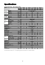
Page 35: ...ration U C F 0 0 12 21 6 12 21 6 0 1 S11 Compressor discharge sensor 4 calibration U C F 0 0 12 21 6 12 21 6 0 1 REGULATOR Type Unit Default Min Max Resolution R1 Cooling set point D C F 12 53 6 R5 R6...

Page 36: ...ure alarm reset type U Flag 1 0 1 1 0 Manual reset 1 Auto reset auto P7 Fan overload alarm reset type U Flag 1 0 1 1 0 Manual reset 1 Auto reset auto P8 Pump overload alarm reset type U Flag 0 0 1 1 0...

Page 37: ...8 8 8 6 WATER LINE HYDRAULIC KIT TYPE PUMP MAX WATER OPER PRESSURE kPa RUNNING CURRENT Amp 1 5 1 5 2 0 2 0 WATER FLOW RATE GPM 17 2 20 7 26 4 31 7 PIPING INSTALLATION PIPE CONNECTION mm in HEAD m 26 2...

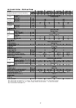
Page 38: ...NING CURRENT Amp 1 5 1 5 2 0 2 0 WATER FLOW RATE GPM 17 2 18 1 20 7 21 7 26 4 28 4 31 7 33 3 PIPING INSTALLATION PIPE CONNECTION mm in HEAD m 26 25 23 5 22 5 25 24 5 23 22 5 COMPRESSOR TYPE POWER SUPP...

Page 39: ...WATER LINE HYDRAULIC KIT TYPE PUMP MAX WATER OPER PRESSURE kPa RUNNING CURRENT Amp 1 5 1 5 2 0 2 0 WATER FLOW RATE GPM 17 2 20 7 26 4 31 7 PIPING INSTALLATION PIPE CONNECTION mm in HEAD m 26 23 5 25...

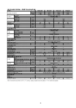
Page 40: ...NNING CURRENT Amp 1 5 1 5 2 0 2 0 WATER FLOW RATE GPM 17 2 18 1 20 7 21 7 26 4 28 4 31 7 33 3 PIPING INSTALLATION PIPE CONNECTION mm in HEAD m 26 25 23 5 22 5 25 24 5 23 22 5 COMPRESSOR TYPE POWER SUP...

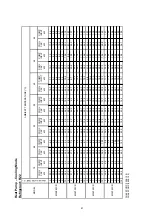
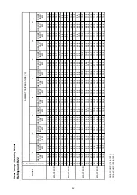
Page 41: ...2 8 4 27 7 9 0 25 1 10 0 24 0 10 4 22 0 11 2 9 31 2 6 5 29 7 8 3 29 0 9 0 28 4 9 6 25 7 10 7 24 7 11 1 22 5 11 9 10 32 1 7 0 30 3 9 1 29 5 10 0 28 9 10 7 26 3 11 6 25 2 11 9 23 1 12 6 5 35 9 6 2 33 9...

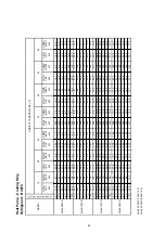
Page 42: ...7 9 30 2 6 8 29 3 8 8 29 0 9 7 28 7 10 4 26 3 11 3 25 3 11 7 23 4 12 5 10 31 0 7 4 30 3 9 7 29 9 10 8 29 7 11 5 27 2 12 3 26 2 12 6 24 2 13 3 5 33 7 6 2 32 4 7 8 31 8 8 5 31 3 9 1 28 6 9 8 27 5 10 1...

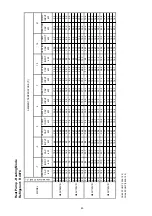
Page 43: ...9 3 41 0 9 8 50 19 0 8 2 20 8 8 3 25 3 8 6 28 9 8 8 31 6 9 0 33 4 9 4 36 4 9 9 40 0 10 6 55 18 1 8 3 19 9 8 5 24 3 8 9 27 8 9 2 30 4 9 4 32 2 9 8 35 3 10 3 39 0 11 0 35 21 1 7 3 23 0 7 5 28 8 8 1 33 5...

Page 44: ...6 7 27 5 9 3 27 2 10 0 26 9 10 4 25 7 10 8 23 7 11 4 20 9 12 3 10 29 4 7 2 28 3 10 0 27 6 10 8 27 3 11 5 26 5 11 6 24 6 12 2 21 5 13 1 5 34 1 6 3 33 4 8 0 32 6 8 7 32 0 9 1 30 4 9 6 28 2 10 2 26 3 11...

Page 45: ...9 28 4 7 0 27 5 9 9 27 2 10 7 26 9 11 1 25 5 11 6 23 9 12 2 22 3 13 0 10 29 2 7 5 28 4 10 7 28 1 11 5 27 8 12 3 26 3 12 4 24 8 13 0 23 0 13 8 5 33 2 6 3 31 7 8 6 31 0 9 4 30 5 9 8 28 9 10 4 26 9 11 1...

Page 46: ...15 5 9 1 17 7 9 2 25 6 9 5 27 3 9 7 28 2 9 9 29 2 10 3 30 5 10 6 34 3 10 7 55 14 8 9 3 16 8 9 4 24 4 9 7 26 6 10 0 27 1 10 3 28 4 10 5 29 6 10 9 33 5 11 1 35 18 6 8 3 22 7 8 4 32 9 8 6 35 3 8 9 36 3...

Page 47: ...28 260 221 1 7 5 7 39 3 5 6 2 43 220 160 2 4 8 7 59 8 6 8 8 61 180 96 3 4 12 2 84 2 7 11 9 82 150 37 4 5 16 3 112 6 MAC M4AC120C CR Flowrate m3 hr Pressure drop psig BPHE kPa Pump head kPa Hydraulic l...

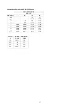
Page 48: ...0 7 9 4 0 827 0 735 6 7 0 88 0 85 0 756 3 9 0 9 0 876 0 781 1 1 0 925 0 925 0 892 0 796 1 7 0 945 0 938 0 906 0 809 4 4 0 956 0 949 0 918 0 82 7 2 0 965 0 959 0 927 0 829 10 0 0 962 0957 0 926 0 828...

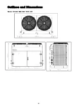
Page 49: ...Outlines and Dimensions Model M4AC MAC080 100 C CR 48...

Page 50: ...Model M4AC MAC120 150 C CR 49...

Page 51: ...Accessory Hydraulic Kit Optional Hydraulic kit consists of 135L capacity water storage buffer tank over pressure release value and drainage point 50...

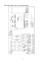
Page 52: ...Wiring Diagrams Model M4AC MAC080 100 120 150C Isolator Switch 51...

Page 53: ...Model M4AC MAC080 100 120 150C Terminal Block 52...

Page 54: ...Model M4AC MAC080 100 120 150CR Isolator Switch 53...

Page 55: ...Model M4AC MAC080 100 120 150CR Terminal Block 54...

Page 56: ...long to moist air 4 Check list before installation servicing x Tubing Refrigerant R407C is more easily affected by dust of moisture compared with R22 make sure to temporarily cover the ends of the tub...

Page 57: ...7C in vapor phase is different from liquid phase f Normally the R407C cylinder or can is being equipped with a dip pipe for liquid withdrawal However if the dip pipe is not available invert the cylind...

Page 58: ...th the national wiring regulation x Ensure that the rated voltage of the unit corresponds to that of the name plate before commencing wiring work according to the wiring diagram x The unit must be GRO...

Page 59: ...be sufficient space allocated for servicing and maintenance when installing the unit Transportation x The unit should be lifted using a crane Ensure that the hanger belts are not touching the coil to...

Page 60: ...oltage Range 380 415V 3Ph 50Hz N Recommended Fuse A 35 40 50 60 Power Supply Cable Size mm 2 Number of Conductor 10 5 10 5 Interconnection Cable Size mm2 1 5 1 5 Heat Pump Unit Model M4AC080CR MAC080C...

Page 61: ...e unit to breakdown x Improper connections and fastening could cause electric shock short circuit and fire x Do not introduce foreign objects such as fingers sticks etc into the air inlet and outlet x...

Page 62: ...t location The handset is located on a metal bracket behind the right door panel 2 LED Display microprocessor board The keypad LED will light up when the unit is powered up The LCD will light up when...

Page 63: ...and cleaning of air intake through the coil surface only These can be done monthly or quarterly depending on the surrounding where the units are installed When the surrounding is very oily or dusty t...

Page 64: ...tion and fault conditions SYMPTOMS POSSIBLE CAUSES REMEDIAL ACTION 1 Compressor does not start x No power supply x Fuses blown or automatic circuit break down open x Defective contactor or coil x Unit...

Page 65: ...Schematic Diagram M4AC MAC080C 100C 120C 150C Refrigerant Circuit Diagram M4AC MAC080CR 100CR 120CR 150CR Refrigerant Circuit Diagram 64...

Page 66: ...5 INS ACCUMULATOR BODY PANEL PARTITION COVER 8 PANEL COIL SUPPORT 26 INS LIQUID RECEIVER 41 SCREW TRUSS PHILIP HEAD 9 PANEL ORIFICE RIGHT 27 PANEL TERMINAL BOX SUPPORT 42 SCREW TRUSS PHILIP HEAD 10 PA...

Page 67: ...SUPPORT 23 ASSY BPHE 39 PLATE PARTITION 8 ASSY TER BOX MAIN 24 PANEL BPHE CLAMP 40 ASSY PANEL HOOK 9 PANEL SUPPORT FRONT 25 SUPPORT TUBE PVC TRUNKING 3 3 0x45 OM710 0 10 SUPPORT WIRE BOARD 26 CLIP FI...

Page 68: ...2004 McQuay International 1 800 432 1342 www mcquay com ISO 9002 REGISTERED...

Reviews: