Caution
!
Please take note of the following important points when installing.
•
Do not install the unit where leakage of flammable gas may occur.
If gas leaks and accumulates around the unit, it may cause fire ignition.
x
Ensure that the drainage piping is connected properly.
If the drainage piping is not connected properly, it may cause water leakage which will dampen
the furniture.
x
Do not overcharge the unit.
This unit is factory pre-charged. Overcharge will cause over-current or damage to the
compressor.
x
Ensure that the units panel is closed after service or installation.
Unsecured panels will cause unit to operate noisily.
Installation Location
x
Installation work should be done by the authorized dealer or qualified contractor. Never install the unit
yourself.
x
Make sure there is sufficient airflow around the unit. The discharged air should be directed outside
using a duct should the unit be installed in a plant room.
x
Vibration isolator should be provided to reduce the vibration and noise of the unit.
x
There should be sufficient space allocated for servicing and maintenance when installing the unit.
Transportation
x
The unit should be lifted using a crane. Ensure that the hanger belts are
not touching the coil, top panel and front panel (use protective panel) as
shown in Figure 1.
x
The bolt of the base and channel support can be removed after putting
the unit on the fixed location.
Figure 1
Water Piping ad Fitting
x
All water pipe must be insulated to prevent capacity losses and condensation.
x
Install a 40-60 mesh strainer to ensure water quality is good.
x
Water pipe recommended are GI pipe, black steel pipe, steel pipe and copper pipe.
x
During installation, the piping of the unit should be clamp before rotating the installation pipe to reduce the
moment induce on the unit piping.
x
Users are recommended to install the pipe and accessories as shown in Figure 2.
x
An air vent must be installed at the highest position, while a drainage plug at the lowest position of the
water circuit. After the leak test (0.6MPa), open the air vent to release any air trap in the water circuit.
x
Run the clean water through the water inlet and operate the pump to drain out the dirty water. Clean
the strainer after running the pump for 30 minutes.
58
Summary of Contents for M4AC 080 C
Page 10: ...5 2 Menu Structure Menu Structure Diagram for Chiller 9...
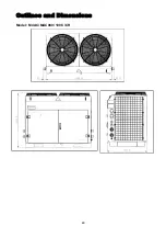
Page 49: ...Outlines and Dimensions Model M4AC MAC080 100 C CR 48...
Page 50: ...Model M4AC MAC120 150 C CR 49...
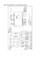
Page 52: ...Wiring Diagrams Model M4AC MAC080 100 120 150C Isolator Switch 51...
Page 53: ...Model M4AC MAC080 100 120 150C Terminal Block 52...
Page 54: ...Model M4AC MAC080 100 120 150CR Isolator Switch 53...
Page 55: ...Model M4AC MAC080 100 120 150CR Terminal Block 54...
Page 68: ...2004 McQuay International 1 800 432 1342 www mcquay com ISO 9002 REGISTERED...

