54
OM
AGSB-5
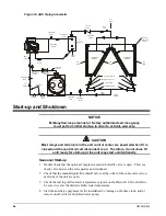
Figure 10, AGS Piping Schematic
DISCHARGE
TUBING
SIGHT
GLASS
AIR
FLOW
WATER OUT
WATER IN
LIQUID
TUBING
EXPANSION
VALVE
SCHRADER
VALVE
CHARGING
VALVE
SIGHT
GLASS
CONDENSER
ASSEMBLY
AIR
FLOW
AIR
FLOW
AIR
FLOW
CONDENSER
ASSEMBLY
CHARGING VALVE
LIQUID SHUT-OFF VALVE
SCHRADER VALVE
FILTER DRIER
OIL
SEPARATOR
OIL
RETURN
DISCHARGE
TUBING
SCHRADER
(EACH DISCH
HEADER)
TO REAR OF
COMPRESSOR
SUCTION
BUTTERFLY VALVE
(OPTION)
RELIEF VALVE
(EVAP SHELL)
RELIEF
VALVE
CHECK
VALVE
ANGLE
VALVE
BALL
VALVE
SOLENOID
VALVE
SIGHT
GLASS
STRAINER
CHARGING
VALVE
SCHRADER
Start-up and Shutdown
NOTICE
McQuayService personnel or factory authorized service agency
must perform initial start-up in order to activate warranty.
CAUTION
Most relays and terminals in the unit control center are powered when S1 is
closed and the control circuit disconnect is on. Therefore, do not close S1
until ready for start-up or the unit may start unintentionally.
Seasonal Start-up
1. Double check that the optional compressor suction butterfly valve is open. There is a
check valve between the oil separator and condenser.
2. Check that the manual liquid-line shutoff valves at the outlet of the subcooler coils on
each side of the unit are open.
3. Check the leaving chilled water temperature setpoint on the MicroTech II controller to
be sure it is set at the desired chilled water temperature.
4. Start the auxiliary equipment for the installation by turning on the time clock, and/or
remote on/off switch, and chilled water pump.
Summary of Contents for AGS 206A
Page 65: ......

