


OM AGSB-5
29
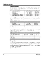
Circuit Controllers:
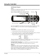
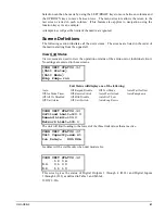
Be sure the pumpdown switch is in the off position. Press the Menu button (the top far right
button with three horizontal lines on it) on the circuit controller. Press the button that
corresponds to “SET”, then press “COMPRESSOR SPs”. Now press the down arrow
button once. Now that you are on the proper screen (SET COMP SPs (2)) you may push the
enter button to go into Change Values Mode for that screen.
You will now see the cursor blinking on the first line, also there will be a “D”, “C”, “+” and
“-” down the right side of the screen. Press the corresponding “+” or “-” button to scroll
through the menu options. You will see “Enable”, “Disable” and “Test”. To select “Test”,
press the enter button. Press the enter button until the cursor scrolls to the top left corner of
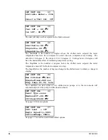
the screen on to the Menu title. Now scroll to the right to the last menu, this menu is the
“Test Circuit” menu. This menu was added when you entered “Test” in the Circuit Mode
field.
“Test Circuit” item #1 is for digital outputs for the fan contactor outputs. The unit is
equipped with fan VFD and fan outputs 1 and 2 will not function. The VFD fans will be
tested later. Press the enter button to go into change values mode. Continue to press enter
until you reach the output you would like to turn on, then press the “+” or “-” turn the
output on or off. Check that each fan is rotating in the proper direction, and does not have
excessive vibration.
“Test Circuit” item #2 is for digital outputs for Slide indicator. You will see a selection to
choose the slide pulse direction, with the options of “Load” (left coil) or “Unload”(right
coil). Then there is a selection to turn the pulse on or off. Choose “on” for the “Pulse” field
and then you can toggle between Load or Unload, checking the corresponding coil to see if
it energizes.
“Test Circuit” item #3 is for digital outputs for the Evaporator oil return line solenoid and
for the EXV close output. Turn the “Oil Return” on and check that the evaporator oil return
line solenoid is energizing. It is located on the base rail behind the suction line connection
to the compressor.
“TEST CIRCUIT” item #4 is for analog outputs for the fan VFD and the EXV. Here you
can ramp up the VFD by adjusting the frequency in the VFD field or manually open and
close the EXV. The EXV operation may be verified by observing operation through the
sight glass on the side of the valve body. Note: Unlike the digital outputs, you must hit
enter for the analog outputs to react to your change.
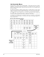
Unit Controller:
At the main menu select “SET”, then select “UNIT SPs”, scroll down 1 screen to screen #2
on the “SET UNIT SPs” screen. You will see “Available Modes”. Change the mode to
“TEST”. (Note: this will disable all running circuits.) Now scroll all the way to the right on
the unit test screen, there is only one screen. Verify the “Alarm Out” output at J15-NO8.
Verify the evap heaters are on by checking the amps on the appropriate wires. Verify the
evaporator pump outputs and wiring by turning the pump outputs on and off.
Note
: When the service test is completed, remember to take both the unit and each of the
circuit controllers out of “Test” Mode and back into “Enable.”
Summary of Contents for AGS 206A
Page 65: ......


