OM AGSB-5
37
Using the Controller
4x20 Display & Keypad
Layout
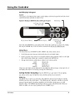
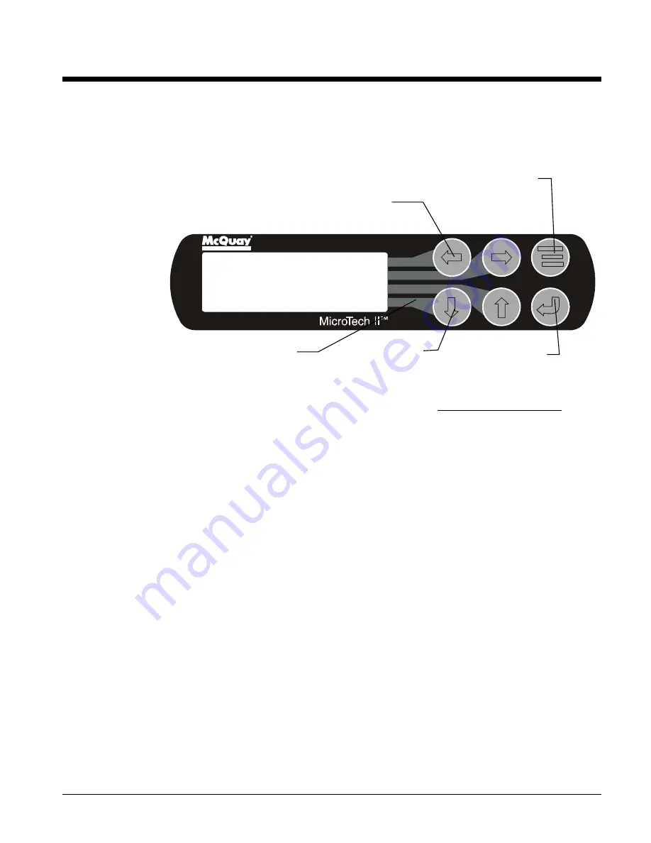
The 4-line by 20-character/line liquid crystal display and 6-key keypad for both the circuit
controller and unit controller is shown below.
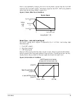
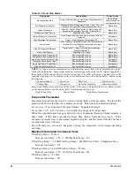
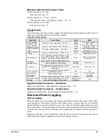
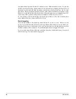
Figure 8, Display (in MENU mode) and Keypad Layout
Air Conditioning
ALARM
VIEW
SET
<
<
<
Note that each ARROW key (except the down arrow) has a pathway to a line in the display.
Pressing an ARROW key will activate the associated line when in the MENU mode.
Arrow Keys
The four arrow keys (UP, DOWN, LEFT, RIGHT) have three modes of use.
1. Scroll between data screens as indicated by the arrows (default mode).
2. Select a specific data screen in a hierarchical fashion using dynamic labels on the right
side of the display (this mode is entered by pressing the MENU key).
3. Change field values in edit mode according to the following table:
LEFT
Default (D)
RIGHT
Cancel (C)
UP
Increment (+)
DOWN
Decrement (-)
These four edit functions are indicated by one-character abbreviations on the right side of
the display (this mode is entered by pressing the ENTER key).
Getting Started, Navigating-
Press the MENU key to get started. The navigating
procedures are the same for both the unit controller and the circuit controller
.
MENU Key
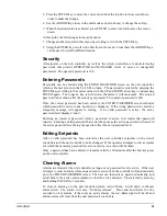
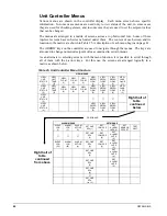
The MENU key is used to switch between the MENU mode as shown in Figure 8 and the
SCROLL mode as shown in Figure 9. The MENU mode is basically a shortcut to specific
groups of menus used for checking ALARMS, for VIEWING information, or to SET
setpoint values. The SCROLL mode allows the user to move about the matrix (from one
menu to another, one at a time) by using the four ARROW keys.
ENTER Key and
Green Comp.
Run Light
MENU Key
ARROW Keys (4)
Key to Screen Pathway
Left Arrow Key and
Red Alarm Light
Summary of Contents for AGS 206A
Page 65: ......


