85
7 TROUBLESHOOTING
Use the following guide to perform simple troubleshooting in case the transponder is not function
accordingly.
Symptom
Possible Cause
Solution
Transponder cannot power
on
Faulty connector to power
Polarity reverse
Power supply current too
low
Check power connection
Check power connection
Check power supply
No picture on display
Unit not powered up
Dimmer level set too low
Press power key
Increase Dimmer level
No map detail
Coastline detail not active
Switch to coastline view
No GPS position data
Antenna or cabling problem
Check antenna cable and
connections
No AIS transmission
MMSI not entered
Transmitter disabled
Power supply voltage too
low
Enter MMSI number
Enable transmitter
Check power supply
No AIS target
VHF cabling problem
Check antenna cable and
connections
AIS range seems too low
VHF antenna and cabling
Check VHF antenna and
cable installation
Sensor ports not response
Cable installation
Check related wiring
Data port not response
Cable installation
Check related wiring
Summary of Contents for 21-100-001A
Page 1: ......
Page 2: ...2 ...
Page 3: ...3 Smartfind M5 Class A Inland AIS Installation and Maintenance Manual ...
Page 12: ...12 2 3 Interconnection Diagram Figure 1 Interconnection Diagram ...
Page 81: ...81 6 MECHANICAL DIMENSIONS 6 1 Smartfind M5 Transponder Main Unit Front size mm Side size mm ...
Page 82: ...82 Back size mm Bottom size mm ...
Page 83: ...83 6 2 Junction Box 6 3 Extension Cable 6 4 Mounting Template not to scale 85 mm 55 mm 165 mm ...
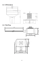
Page 84: ...84 6 5 GPS Antenna 6 6 Pilot Plug 2 m 60 mm 40 mm 60 mm 80 mm 103 92 mm ...
Page 112: ...112 Note ...
Page 113: ...113 21 135 001N Issue 15 ...
Page 114: ......


