


33
4.2.2 Coastal View
Figure 19
Coastal View
Item
Function
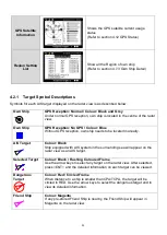
Own Ship
information
Own-ship information for latitude, longitude, SOG and COG
Target
information
Display the target information such as vessel name or MMSI as well as range
and bearing relatively to the own ship
Function Icon
(Coastal View)
Users can select one of the 5 viewing modes by pressing the FUNC button.
Turn the knob to change the selected range, position, AIS target or
SART/MOB target
Zoom In/Out:
The plot range can be adjusted by turning the knob which cycles through the
ranges 24, 12, 6, 3, 1.5, 0.75, 0.5, 0.25, 0.125 and 0.05nm.
Up/Down:
Turn the knob to move the map vertically
Left/Right:
Turn the knob to move the map horizontally
Target Selected:
Turn the knob to navigate between different AIS targets, press the knob to
see more details of the target.
SART/MOB:
This icon appears only when valid SART or MOB target is received. Turn the
knob to navigate between different SART/MOB targets, press the knob to
see more details of the target.
The coastline map in this transponder is neither verified nor approved by
Hydrographic Authorities. It is not an Electronic Chart System and therefore
should not be used for navigation. The information provided by the coastline map
is for reference only and should be used together with other navigation sources
and devices.
Targets Received :10
12.00Kn
241.0°
53°08’56”N
4°57’00”E
MY SHIP
RNG 39.54NM
BRG +320.53°
12 NM
52°30’N
53°00’N
53°30’N
4°00’E
5°00’E
2013/01/17 07:18:11
Own Ship
information
Target
information
Function
Icon
Selected
Target
Summary of Contents for 21-100-001A
Page 1: ......
Page 2: ...2 ...
Page 3: ...3 Smartfind M5 Class A Inland AIS Installation and Maintenance Manual ...
Page 12: ...12 2 3 Interconnection Diagram Figure 1 Interconnection Diagram ...
Page 81: ...81 6 MECHANICAL DIMENSIONS 6 1 Smartfind M5 Transponder Main Unit Front size mm Side size mm ...
Page 82: ...82 Back size mm Bottom size mm ...
Page 83: ...83 6 2 Junction Box 6 3 Extension Cable 6 4 Mounting Template not to scale 85 mm 55 mm 165 mm ...
Page 84: ...84 6 5 GPS Antenna 6 6 Pilot Plug 2 m 60 mm 40 mm 60 mm 80 mm 103 92 mm ...
Page 112: ...112 Note ...
Page 113: ...113 21 135 001N Issue 15 ...
Page 114: ......