21
3.8 External Connectors (Junction Box)
Figure 10
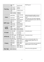
External Connectors (Junction Box)
CONNECTOR
LABEL
NAME
DESCRIPTION
FUNCTION USAGE
Sensor 1
SEN1_IN
GND
Sensor 1 ground
Connect to data sources such as
heading, gyro, or other type of
sensors.
SEN1_IN A
Sensor 1 input A
SEN1_IN B
Sensor 1 input B
Sensor 2
SEN2_IN
GND
Sensor 2 ground
Connect to data sources such as
heading, gyro, or other type of
sensors.
SEN2_IN A
Sensor 2 input A
SEN2_IN B
Sensor 2 input B
Sensor 3
SEN3_IN
GND
Sensor 3 ground
Connect to data sources such as
heading, gyro, or other type of
sensors.
SEN3_IN A
Sensor 3 input A
SEN3_IN B
Sensor 3 input B
Cable Glands
Sensors 1~3
DGPS
sensor
DISP
Alarm
Pilot plug
LR
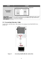
Jumper for
NMEA2000
shield and
ground
Termination
switches
To Transponder Main Unit
NMEA 2000
Blue Sign
Frame
Ground
Frame Ground
Strip
Summary of Contents for 21-100-001A
Page 1: ......
Page 2: ...2 ...
Page 3: ...3 Smartfind M5 Class A Inland AIS Installation and Maintenance Manual ...
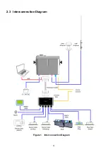
Page 12: ...12 2 3 Interconnection Diagram Figure 1 Interconnection Diagram ...
Page 81: ...81 6 MECHANICAL DIMENSIONS 6 1 Smartfind M5 Transponder Main Unit Front size mm Side size mm ...
Page 82: ...82 Back size mm Bottom size mm ...
Page 83: ...83 6 2 Junction Box 6 3 Extension Cable 6 4 Mounting Template not to scale 85 mm 55 mm 165 mm ...
Page 84: ...84 6 5 GPS Antenna 6 6 Pilot Plug 2 m 60 mm 40 mm 60 mm 80 mm 103 92 mm ...
Page 112: ...112 Note ...
Page 113: ...113 21 135 001N Issue 15 ...
Page 114: ......

