


68
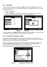
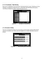
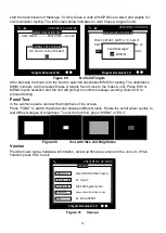
4.11.1 Customize
Customize provides personalization settings:
Dimmer Level - brightness setting from 1 (low) to 100 (high)
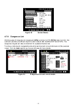
Colour mode - brightness and contrast adjustment for the LCD display along with selection
of day or night operating mode. In night mode the display colours are inverted (light text on
a dark background).
Key time-out - time to leave menu screen and switch back to coastal view
Language - available: select the user interface language from the available language
options.
Key Beep – turn on or off the key beep
Time Zone – set the time zone
SART test mode – hide or display the SART test message
NMEA 2000 device instance is used to identify multiple similar products connected on the
same NMEA 2000 network. The setting value is between 000 and 252.
Coordinate Format – user can choose between DD
°
MM.SS” (degrees, minutes, seconds)
and DD
°
MM.mm´ (degrees, minutes, decimal minutes) to display the vessel coordinate.
Figure 73
Customize
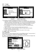
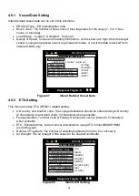
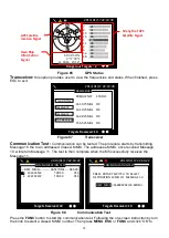
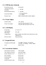
4.11.2 Radar View
This setting provides user the ability to centre the radar map on given coordinates.
Turn
knob
to choose either latitude or longitude and press
knob
to confirm. Once pressed, turn
knob
to choose a parameter and press
knob
again to enter input mode. When finished, press
ESC
to return to the level before. Continue these procedures till all settings are set.
Figure 74
Radar View Setting
CUSTOMIZE
2013/01/17 22:43:39
Targets Received: 10
COLOUR MODE <Day>
KEY TIME-OUT [1] (1~5 min)
LANGUAGE <English>
DIMMER LEVEL
[100] Lo………………………Hi
KEY BEEP <None>
Time Zone
<GMT>
SART TEST MODE <OFF>
COORDINATE FORMAT <DD
°
MM’SS”>
NMEA 2000 DEVICE INSTANCE [000]
RADAR VIEW SETTING
2013/01/17 22:43:39
Targets Received: 10
Latitude
[
53]
°[08]’[56]”<N>
Center position of radar view
Longitude
[057]
°[00]’[00]”<W>
RADAR VIEW ORIENTATION
MODE
<NORTH UP>
Summary of Contents for 21-100-001A
Page 1: ......
Page 2: ...2 ...
Page 3: ...3 Smartfind M5 Class A Inland AIS Installation and Maintenance Manual ...
Page 12: ...12 2 3 Interconnection Diagram Figure 1 Interconnection Diagram ...
Page 81: ...81 6 MECHANICAL DIMENSIONS 6 1 Smartfind M5 Transponder Main Unit Front size mm Side size mm ...
Page 82: ...82 Back size mm Bottom size mm ...
Page 83: ...83 6 2 Junction Box 6 3 Extension Cable 6 4 Mounting Template not to scale 85 mm 55 mm 165 mm ...
Page 84: ...84 6 5 GPS Antenna 6 6 Pilot Plug 2 m 60 mm 40 mm 60 mm 80 mm 103 92 mm ...
Page 112: ...112 Note ...
Page 113: ...113 21 135 001N Issue 15 ...
Page 114: ......