background image

30 


MBW 473 Manual English V5.0 

5.4   Control Setup


Using the 

Control Setup

 menu enables you to control the manner in which the 473 operates. 

Dew / Frost Control 

When measuring dew/frost points between 0 °C and -

20 °C, condensation on the instrument’s chilled 

mirror may be  in the form of dew, frost, or a combination of both.  If the state of the condensation is 
not known, it will introduce errors into all the humidity measurements reported by the instrument. 

To eliminate this potential source of error, the Force Frost function is used to rapidly cool the mirror to 
below -20 °C, forcing all dew on the mirror into frost. The mirror will then re-stabilize at the frost point 
temperature. Once the condensate layer is in a state of frost, it will remain frost for all sub-zero mirror 
temperatures,  allowing  the  instrument  to  measure  the  frost  point  accurately.  The  dew  point  and  all 

other humidity measurements are then mathematically calculated from the frost point.  


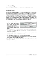
To change the 

Force Frost 

settings: 

1.  Select  the 

Control  Setup

  menu  by 

pressing  the  dark  gray  menu  selection 
key until 

Control Setup

 appears. 

2.  Touch  the 

Dew/Frost  Control

  button.  

The  Mirror 

Dew/Frost  Control

  window 

will open. 

3.  The Force Frost function can be enabled or disabled by clicking on the 

Force Frost Below

 button. 

If  the  indicator  on  the  left  side  of  the  button  is  green,  Force  Frost  is  enabled.    If  the  indicator  is 
grey, Force Frost is disabled. 

4.  To adjust the temperature below which Force Frost activates, click on the 

Change To

: field to the 

right of the Force Frost Below button. The field will turn white. 

5.  Enter the temperature in degrees C below which Force Frost should activate. 

6.  If you make an entry error, touch the field that holds the number you wish to change.  Each time 

you touch the field, the last digit entered will be deleted. 

Press the 

OK

 button in the dialog box or press Enter on the keypad to confirm the new value.  Press 

Cancel to leave it unchanged. 


Summary of Contents for 473-RP2

Page 1: ...Operation and Maintenance Manual V5 0 Dew Point Mirror 473...

Page 2: ......

Page 3: ...rized representatives may void all warranties Warranty may also be voided for misuse neglect accident corrosion and improper installation This Warranty is exclusive and in lieu of any and all other wa...

Page 4: ...ii MBW 473 Manual English V5 0...

Page 5: ...el 9 4 2 Touch Screen 12 4 3 Back Panel 13 4 4 Measuring Heads 18 4 5 Carrying Handle 23 5 SYSTEM CONFIGURATION 25 5 1 The Menu 25 5 2 Selection of indicated Parameters 26 5 3 Selection of Numeric or...

Page 6: ...52 8 MAINTENANCE 55 8 1 Calibrate the Touch Screen 55 8 2 Mirror Cleaning 56 8 3 Exterior Cleaning 57 8 4 Peltier Cooling Test 58 8 5 Periodic Maintenance Checks 58 9 ERROR MESSAGES 59 9 1 Reversible...

Page 7: ...housing or connecting disconnecting sensors Measuring head may get hot during operation Instruments built for the SH3 measuring head supply more power through the measuring head cable Therefore you m...

Page 8: ...2 MBW 473 Manual English V5 0...

Page 9: ...the calculation of relative humidity Optional Pressure Measurement Optionally the 473 can be ordered with internal pressure measurement capability This enables the user to measure barometric pressure...

Page 10: ...4 MBW 473 Manual English V5 0...

Page 11: ...easuring head and a 3 m cable to connect the probe direct ly to the back panel of the instrument o The SH2 is supplied with a 2 x 100 mm PRT and a 0 5 m cable to connect the probe to the measuring hea...

Page 12: ...coefficients must be changed accordingly 3 2 Installing the Measuring Heads The heart of the 473 Dew Point Mirror Instrument is a highly sensitive and accurate measuring head Depending on your order t...

Page 13: ...ternal Temperature Probe on page 16 Alternatively a fixed external temperature value may be entered via the touch screen Please follow the instructions in section 6 2 External Temperature You can test...

Page 14: ...8 MBW 473 Manual English V5 0 SH2 SHX Fan Fan...

Page 15: ...ion on or off simply touch the desired key or object directly on the screen When the 473 is turned on the display will activate within a few seconds A sample display configura tion is shown below The...

Page 16: ...below center The faster it disappears the lower the indication When the indicator is in the center the thickness of the dew or frost layer is neither growing nor evaporating and the layer on the mirr...

Page 17: ...menu selection is circular Once you go past the last menu the first one will appears again and the process starts over You can use the key on the keypad to move backward through the menus Use the Ent...

Page 18: ...h functions on or off touch the screen where appropriate with your finger or a stylus Never use sharp objects as damage may occur Before using the 473 for the first time or when several users operate...

Page 19: ...MBW 473 Manual English V5 0 13 4 3 Back Panel Without Options With Barometric Pressure and Analog Output Options...

Page 20: ...nnection The 473 can be ordered with different types of measuring heads the RP2 SH2 SH3 and SHX These measuring heads are connected to the back panel of the corresponding 473 display unit The 473 RP2...

Page 21: ...he output signal is connected to a D A converter and then split into a voltage and a current signal There fore you may use either a volt or current meter to receive the analog signal The maximum volta...

Page 22: ...ead 2 Use the supplied 4 pin 0 5 m cable to connect the probe to the measuring head 3 Use the supplied 5 pin 3 m cable to connect the probe directly to the back panel of the instrument The SHX is supp...

Page 23: ...housing is located directly above pin 1 Pin Signal Position Description 1 Shield When viewing the solder tabs of a disassembled 5 pin LEMO connector pin 1 is usually identified with a full or partial...

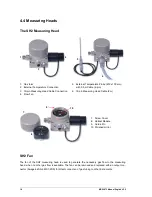
Page 24: ...5 m Cable 4 pin 6 19 pin Measuring Head Cable 2 m 7 Screw Cover 8 Optical Module 9 Guide Pin 10 Polished mirror SH2 Fan The fan of the SH2 measuring head is used to generate the necessary gas flow to...

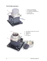
Page 25: ...4 pin 6 30 pin Measuring Head Cable 2 m 7 Screw Cover 8 Optical Module 9 Guide Pin 10 Polished Mirror SHX Fan The fan of the SHX measuring head is used to generate the necessary gas flow to the measu...

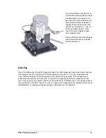
Page 26: ...ad 1 Gas Inlet 6 mm Swagelok 2 Gas Outlet 6 mm Swagelok 3 15 pin Measuring Head Cable 2 m 4 2 pin Fan Cable 5 Measuring Head Fan 1 2 3 4 5 6 15 pin Measuring Head Cable Connector 7 Screw Cover 8 Optic...

Page 27: ...One of the differences of the SH3 measuring head to the SH2 measuring head is that it does not have a sample gas flow fan The purpose of the fan installed on the SH3 is to cool the measuring head bas...

Page 28: ...473 SH3 473 SHX Use only the corresponding measuring head for each display unit otherwise it will cause damage to the instrument The SHX version is equipped with a 30 pin measuring head connection ins...

Page 29: ...Carrying Handle To adjust the position of the carrying han dle press the buttons on both sides Re lease the buttons when the handle is in the desired position Ensure that the handle has locked into pl...

Page 30: ...24 MBW 473 Manual English V5 0...

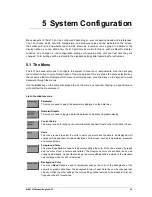
Page 31: ...red Staying in a specific menu will not affect the measurement List of available menus Parameter This menu is used to select the parameters displayed on the data lines Numeric Graphic This menu is use...

Page 32: ...RH The ratio between the amount of water vapor in a sample and the maximum amount possi ble at that same temperature and pressure RH WMO The ratio between the amount of water vapor in a sample and th...

Page 33: ...quire the measuring head to be connected such as Frost Point Dew Point Head Temp RH Humidity Volume Ratio Weight Ratio Vapor Pressure or Head Pressure please make sure all the relevant equipment is co...

Page 34: ...key on the numeric key pad to confirm Press the Cancel button if you wish to abort all changes made in the dialog box Any values you enter will only be accepted by the system if they correspond with...

Page 35: ...ge the time span the data that was sampled and stored at the old interval will be in crementally replaced by new data sampled at the new interval The time span indicated on the graph will always refle...

Page 36: ...all other humidity measurements are then mathematically calculated from the frost point To change the Force Frost settings 1 Select the Control Setup menu by pressing the dark gray menu selection key...

Page 37: ...t it is also possible that dew and frost exist concurrently on the mirror which results in a non stable value reading somewhere between the dew and frost point Therefore the phase of the condensate mu...

Page 38: ...that holds the number you wish to change Each time you touch the field the last digit entered will be deleted 6 Press the OK button in the dialog box or press Enter on the keypad to confirm the new va...

Page 39: ...ld before allowing the next dew or frost point measurement A heating time of 0 means that the instrument will resume dew or frost point measurement immediately upon reaching the mirror check temperatu...

Page 40: ...ish to change Each time you touch the field the last digit entered will be deleted Press the Ok button in the dialog box or press Enter on the keypad to confirm the new value Press Cancel to leave it...

Page 41: ...ata retrieved via RS 232 will always be in SI units regardless of the units chosen for display Also note that settings within dialog boxes used for changing system parameters are entered and displayed...

Page 42: ...pointing arrows Note that each of the upper keys correspond to the data lines they point to 2 Press the arrow key of the data line you wish to change Note that the foreground color of the data line w...

Page 43: ...read the three following subsections 4 Follow the same procedure for the sec ond or any subsequent analog outputs as needed Selection of Parameter to Track In the analog configuration window enter the...

Page 44: ...1 VDC on the analog out put to represent the 0 100 RH Enter 0 into the field next to the Min Voltage and 1 into the field next to Max Voltage Example 2 To keep things simple we will take the same Para...

Page 45: ...suspect that there may be an error with the instrument The mirror must be visible to perform the Ice Test If you have an SH2 SH3 or SHX measuring head remove the measuring head cover prior to the Ice...

Page 46: ...ase transition When you observe the phase transition on the mirror press the Ok button The mirror temperature is measured at that moment and a dialog box appears with the test results If the measured...

Page 47: ...wn in seconds until the test ends The duration of the test is two minutes TH Temperature of the measuring head TM Actual temperature of the mirror TMdelta Delta between head temperature and mirror tem...

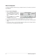
Page 48: ...ay menu selection key until Diagnostics Functions ap pears 2 Touch the RS 232 button The RS 232 Configuration window will open 3 To change the baud rate value touch the gray Change To field The field...

Page 49: ...Set Up and Operation 6 1 Measurement Set Up Back Panel Connections The following picture shows the back panel of a fully connected 473 with RS 232 cable 19 pin meas uring head cable power cable and th...

Page 50: ...rature Enter the desired temperature in degrees Celsi us 21 C in this example and activate the Use Fixed Ext Temp option by touching the button When the indicator square turns green the fixed external...

Page 51: ...properties of the measuring head and any items in its environment and their possible effects The following application examples are included to show some of the most common applications of the 473 In...

Page 52: ...inherent stability and precision the uncertainty can be significantly improved The 473 RP2 is ideal for this application As shown the RP2 measuring head is introduced into the generator chamber throu...

Page 53: ...sufficient according to IEC 60068 When comparing for example RH probes to the RP2 probe mounted in an RH generator chamber it is reccomended that there is at least 10mm of clearance between the probes...

Page 54: ...rature measurement system may not be practical for site engineers as they need to run calibrations quickly to minimize down time Examples of this situation include calibration of instru ments used in...

Page 55: ...t connector rather than a 9 pin connector you will also need a 25 pin to 9 pin port adapter Both the 9 pin RS 232 extender cable and the 25 pin to 9 pin port adapter are commonly available at most com...

Page 56: ...3 will be shown in this font General Use All commands require a question mark to indicate you are requesting data When requesting data from the 473 follow the command with the question mark character...

Page 57: ...tation Receiving a number as 12 34 is the same as receiving it as 1234e 2 or as 1 234e1 Depending on the value of numerical responses the 473 sends out it may send the numbers in either standard or sc...

Page 58: ...fic Humidity g kg VP Vapor Pressure Pa P Head Pressure Pa Tx External Temperature C Tm Mirror Temperature C Th Head Temperature C Om Mirror PRT Resistance Ohms Ox External PRT Resistance Ohms System I...

Page 59: ...tivates AMC 0 disables AMC AMC cycleTime n AMC cycle time in minutes AMC heatTime n AMC heating hold time in minutes AMC temp n Target temperature during AMC C AMC dispHold i 1 enables frost dew point...

Page 60: ...converter is calibrated Automatically sets to Ana1 hold 1 If calibration done Ana1 hold must be sent 0 Ana1 hold i 1 calibration mode Analog output is set with the command Ana1 output n 0 normal mode...

Page 61: ...key on the numerical keypad for 3 to 4 seconds You will hear two short beeps and the key in the upper right corner will turn yellow With the tip of your finger press the center of the yellow key in t...

Page 62: ...red knurled knob To remove it simply turn it counterclockwise It re quires approximately three full turns to completely unscrew it Once the screw cover has been removed remove the black optical module...

Page 63: ...opto electronic ele ments and gold contacts The other half con tains the mirror temperature sensor and some mating gold contacts Avoid touching the mirror and gold contacts with your fingers to preven...

Page 64: ...ou can check this with the Peltier Cooling Test PCT function Please follow the instructions in section Peltier Cooling Test on page 41 8 5 Periodic Maintenance Checks Apart from periodic mirror cleani...

Page 65: ...Chamber temperature may be too high Try again after several minutes if it fails again contact MBW service 9 2 Irreversible Error Messages Error Message Explanation Possible Reasons and Solutions ERROR...

Page 66: ...lay unit does not recog nize a fan No fan is mounted to the measur ing head There is a cable break between the display unit and the fan Con tact MBW service Fan supply failure The fan driver in the di...

Page 67: ...ation certificate RS 232 5 7 LCD with color touch screen Platinum Resistance Thermometer IEC 60751 2008 2 5 m English Factory calibration 5 points FP DP 3 points temperature Optional Internal barometr...

Page 68: ...62 MBW 473 Manual English V5 0...

Page 69: ...MBW 473 Manual English V5 0 63 11 Drawings 11 1 Display Unit Side View...

Page 70: ...64 MBW 473 Manual English V5 0 Front View Back View...

Page 71: ...MBW 473 Manual English V5 0 65 11 2 Measuring Heads RP2 SH2...

Page 72: ...66 MBW 473 Manual English V5 0 SHX SH3...

Page 73: ...MBW 473 Manual English V5 0 67...

Page 74: ...68 MBW 473 Manual English V5 0...

Page 75: ...y was configured incorrectly and I would like to go back to factory default Solution Press and hold key number 7 or 8 on the keyboard for 3 4 seconds This enables you to restore the factory default se...

Reviews: