46
MAX Arm/Ultra Arm V1
OPENING Direction
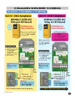
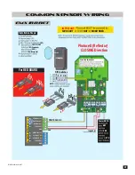
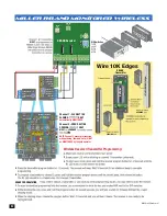
Photocell (Reflector)
10K Resistor Wiring to E3K Photocell
IMPORTANT:
Photocell
MUST be in alignment
with reflector or fault
will occur.
4 5 6
C-1
C-2
NO1
NC1
NC2 NO2
LIGHT ON
SENSITIVITY
Min
Max
DARK ON
Power
Set switch to
“LIGHT ON”
24 to 240 VAC
24 to 240 VDC
1
Com
2
NO
3
NC
Sensitivity Adjustment:
If the photocell does not respond to an
obstruction, lower the sensitivity by
turning adjustment counter-clockwise.
12VDC OUT Monitored
OK to
use
12VDC
PHOTO CLS NC
GND
Installation Steps:
1. Set switch to “LIGHT ON”
2. Wire 12V power to photocell
3. Wire PHOTO CLS NC
to photocell NO1
Wire
GND to photocell C-1
4. Align photocell to reflector
5. Adjust sensitivity
DO NOT
connect
to NC1 #3.
OPEN ONLY
NC
OPEN ONLY
10K
PHOTO CLS
NC
OPEN/CLS
NC
GND
12VDC OUT
GND
CLS ONLY
10K
OPEN/CLS
10K
12VDC OUT
UL SENSOR N.C.
UL SENSOR 10K
O
C
OR 10K
O
OR 10K
O
OR 10K
O
OR 10K
O
OR 10K
R 10K
R 10K
R 10
R 10
Polarity does NOT matter
UL 2018 Label on packaging
NOTE: To meet the UL 325 2018 standard,
Type B1 Non-Contact sensor entrapment
protection device MUST be MONITORED
by the gate operator.
****NEW!!!****
E3K with Built-In Resistor to comply with
UL325-2018 Requirements
** Please consult enclosed wiring diagrams
and operator instruction manual**
IMPORTANT:
Photocell MUST be powered by
12VDC OUT or it will NOT be MONITORED.
OMRON E3K-R10K4 Wiring
UL325 - 2018 Compliance
DSP Arm Controller
Summary of Contents for MAX ARM
Page 2: ......


